4. wiring and installation
4.1 Wiring
4.1.1 Overview
is protected from ESD (static electricity), so no special protection from ESD is needed during mounting.
Dismount the potentiometer plate (use a standard 4 mm Allen key), and the connection terminals will be visible. Be careful
not to damage the gasket when the potentiometer plate is dismounted from the housing.
Cable dimensions between 0.2 and 2.5 mm2 multi-stranded or max. 4 mm2 single-stranded can be used for the screw
terminals. Cable entry is obtained via three PG21 glands. Cable dimensions mm is possible with PG21 gland.
NOTE
The PG glands cannot be changed to another size or type, as they are a vital part of the IP66 protection.
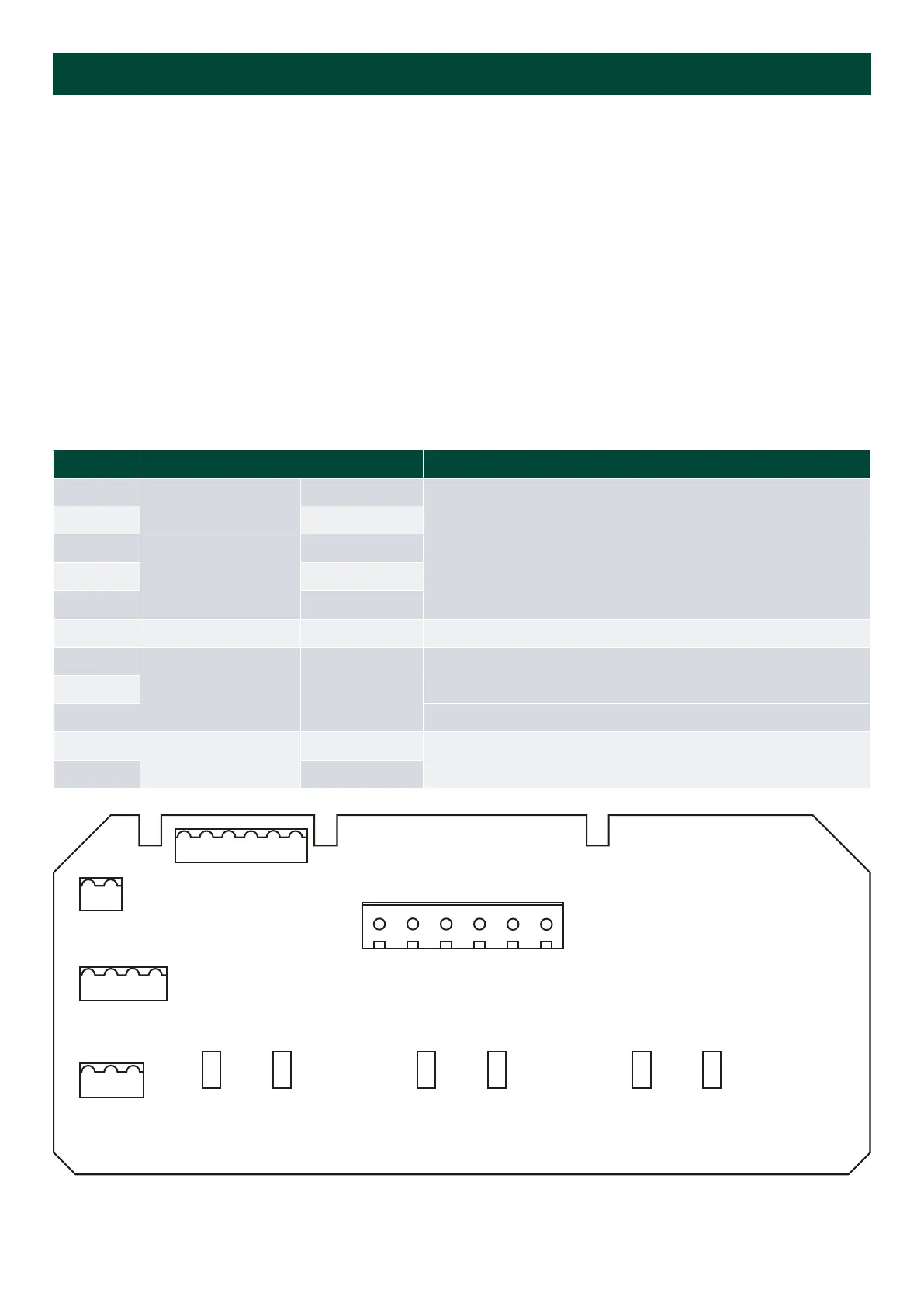
4.1.2 Analogue input terminal overview
Pin number Function Note
1
Supply voltage
0 V
2 24 V
3
Analogue input
Input 1 (Sin)
Input 1 and GND used for single input
On 4 to 20 mA, input 1 is CW and input 2 CCW
Note: GND is mutual for input 1 and input 2
4 GND
5 Input 2 (Cos)
8 NC No connection
9
X4 connector
Illumination
Orange wire
Brown wire
Red wire
Dimmer potentiometer kOhm)
10
11 Wiper on the dimmer potentiometer
A
Analogue adjustment
Max. adjustment
Max. and min. adjustment, sealed by label Located on the rear of
the XL192
B Min. adjustment
X3
X5
X6
X4
9 11 10
8 5 4 3 2 1
0 V
24 V
INPUT 1
GND
INPUT 2
NC
X1
Installation and commissioning guide 4189350024O EN Page 20 of 39

 Loading...

