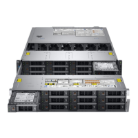
Figure 51. Connecting the cable to internal PERC riser
2 Holding the blue touch points, align the slot on the internal PERC riser to the guide on the system board.
3 Insert the internal riser card’s edge connector rmly into the system board connector until the riser is fully seated.
4 Lift the plunger to lock the riser in place.
Figure 52. Installing internal PERC riser
5 Connect the cables to the backplane and then route the cables to the cable guiding latch to close the latch.
Next steps
1 Install the air shroud.
2 Follow the procedure listed in After working inside your system.
Related links
Installing the air shroud
94
Installing and removing system components
 Loading...


