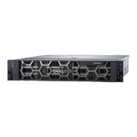
1 Front view of the 24 x 2.5-inch drive system.........................................................................................................15
2 Front view of the 16 x 2.5-inch drive system......................................................................................................... 15
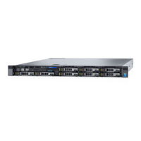
3 Front view of the 8 x 2.5-inch drive system........................................................................................................... 16
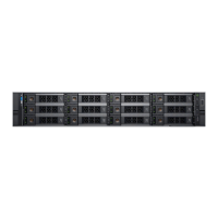
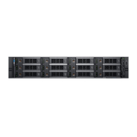
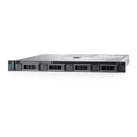
4 Front view of the 12 x 3.5-inch drive system..........................................................................................................16
5 Front view of the 8 x 3.5-inch drive system........................................................................................................... 17
6 Left control panel without optional iDRAC Quick Sync 2 indicator......................................................................18
7 Left control panel with optional iDRAC Quick Sync 2 indicator........................................................................... 18
8 Right control panel view............................................................................................................................................ 19
9 Rear view of the system........................................................................................................................................... 20
10 Rear view of the system with 2 x 2.5-inch rear drive module.............................................................................. 21
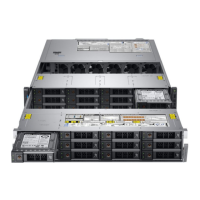
11 Inside the system....................................................................................................................................................... 22
12 Inside the system with full length risers.................................................................................................................. 23
13 Locating the Express Service Code and Service tag............................................................................................ 24
14 Service information....................................................................................................................................................25
15 Memory information and system board connectors............................................................................................. 26
16 LED behavior, configuration and layout, express service tag for 2.5-inch HDD system..................................26
17 LED behavior, configuration and layout, express service tag for 3.5-inch HDD system.................................. 27
18 Removing the front bezel......................................................................................................................................... 48
19 Installing the front bezel............................................................................................................................................49
20 Removing the system cover.....................................................................................................................................50
21 Installing the system cover........................................................................................................................................51
22 Removing the drive backplane cover...................................................................................................................... 52
23 Installing the drive backplane cover........................................................................................................................ 53
24 Removing the right control panel............................................................................................................................ 54
25 Installing the right control panel...............................................................................................................................55
26 Removing the left control panel...............................................................................................................................56
27 Installing the left control panel................................................................................................................................. 57
28 Removing the air shroud........................................................................................................................................... 58
29 Installing the air shroud............................................................................................................................................. 59
30 Removing the GPU air shroud................................................................................................................................. 60
31 Installing the GPU air shroud.....................................................................................................................................61
32 Removing the GPU air shroud top cover................................................................................................................62
33 Installing the GPU air shroud top cover.................................................................................................................. 63
34 Removing the cooling fan cage assembly...............................................................................................................64
35 Installing the cooling fan cage assembly................................................................................................................. 65
36 Removing a cooling fan.............................................................................................................................................66
37 Installing a cooling fan................................................................................................................................................67
38 Removing the side wall bracket............................................................................................................................... 68
39 Installing the side wall bracket..................................................................................................................................69
40 Removing a drive blank............................................................................................................................................. 70
Figures
Figures 7

 Loading...


