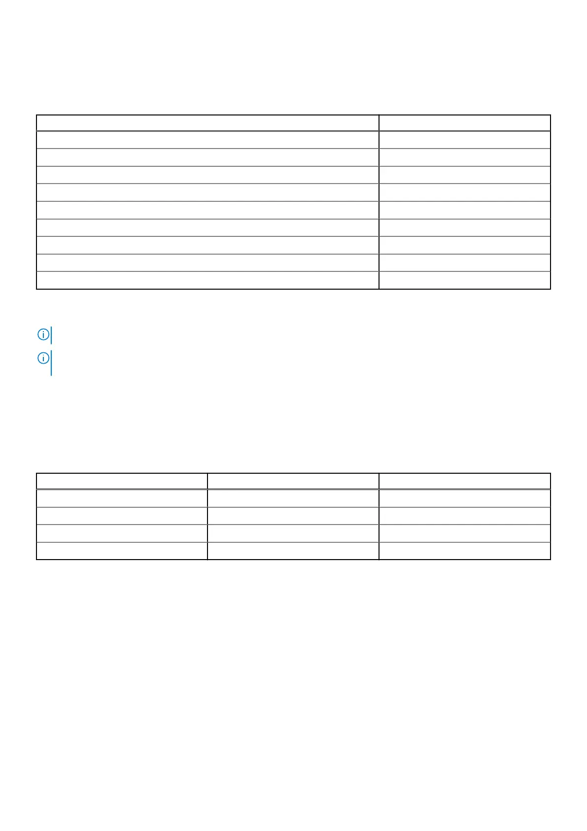
Matrix of expansion modules
Table 2. Expansion modules
Module Connection
4G
a
M.2 2280
5G
a
M.2 2280
WiFi AX210
b
- default mPCIe
uFM - 2x COM RS-422/485 mPCIe
uFM - 2x COM RS-232 mPCIe
uFM - 2x GbE with PoE mPCIe
uFM - 2x GbE LAN mPCIe
uFM - 2x Canbus mPCIe
uFM - 8x DI/O Internal I2C wafer
a.
Requires an M.2 2280 B+M key to M.2 3042 B-key adapter.
b.
Requires an mPCIE to M.2 2230 A+E key adapter.
NOTE: uFM can only support one unit at a time due to the shared I/O panel bracket.
NOTE: Installation of a uFM module requires removal of COM3 and COM4 ports. With the exception of the 8x DI/O
module, it also requires removal of WiFi.
Display options
With computing and graphic performance enhancement from its 9th Generation Intel processors, the EGW-5200 controller can
support three independent displays with the following configurations.
Table 3. Maximum available resolution display configurations
Option Port Resolution
Display option 1 DisplayPort1 4096 x 2304 @ 60 Hz
Display option 2 DisplayPort2 4096 x 2304 @ 60 Hz
Display option 3 DVI-D 1920 x 1200 @ 60 Hz
Display option 4
a
VGA 1920 x 1080 @ 60 Hz
a.
Disabled when all other video ports are connected.
10 Specifications
 Loading...