DC power input
Figure 14. DC power input
Table 13. DC power input pin definitions
Pin Signal
1 V+ (DC_IN)
2 V– (DGND)
See Attach DC power connector on page 26 to install the DC power connector to the DC power input. Connect the chassis
ground screw to an appropriate grounding point.
Table 14. Power source rating
Source Voltage Current
DC power source 12 to 24 VDC 12 A to 6 A min.
AC-to-DC adapter 24 VDC 6 A min.
CAUTION: Before providing DC power, ensure the voltage and polarity provided are compatible with the DC
input. Use an approved power source as certified by IEC or UL. Improper input voltage and/or polarity can be
responsible for system damage.
COM port connectors
The EGW-5200 provides four COM ports through D-sub 9-pin connectors. The COM1 and COM2 ports support
RS-232/422/485 modes by BIOS setting, while COM3 and COM4 are located on the uFM modules and support only RS-
232.
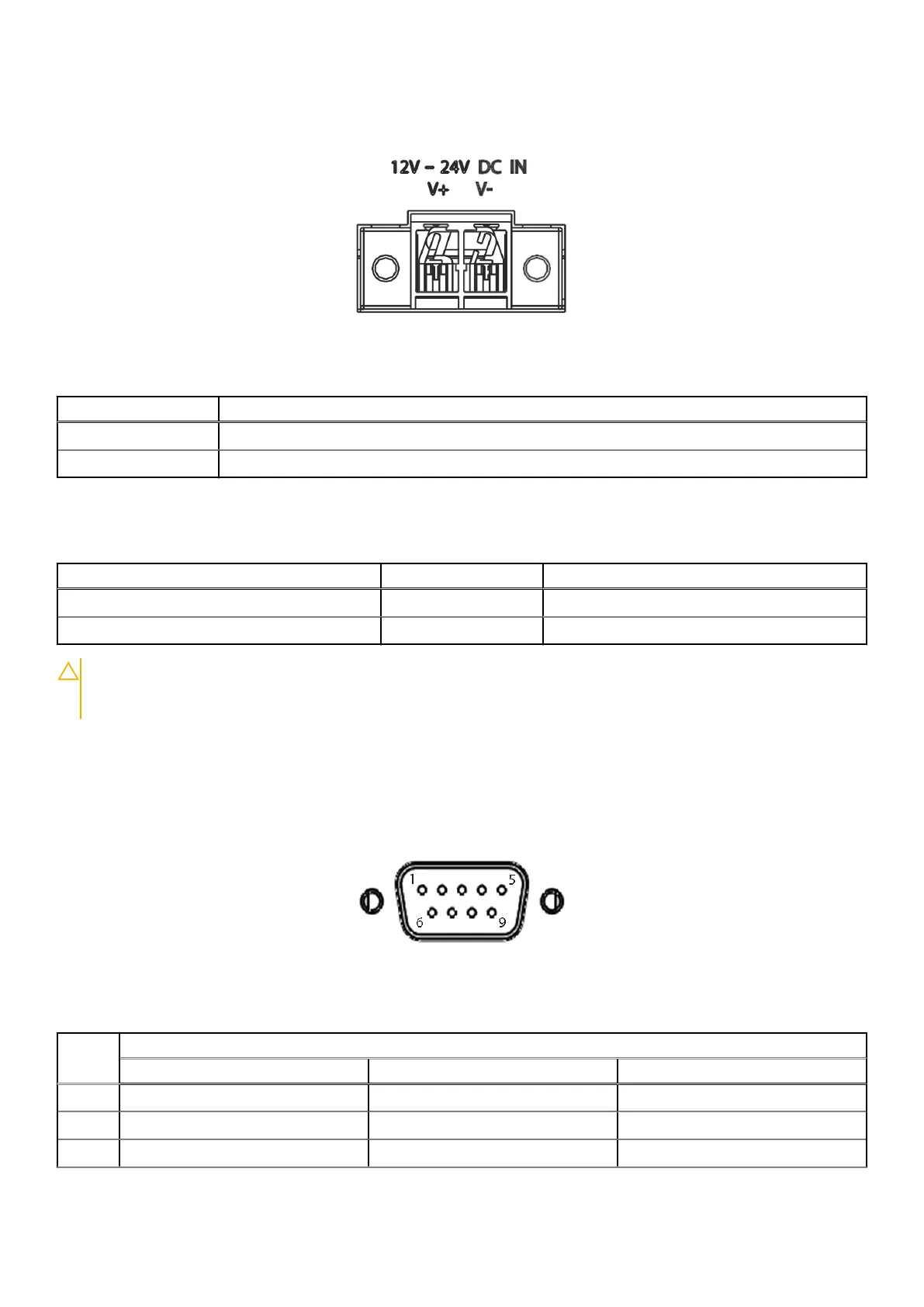
Figure 15. COM port pin locations
Table 15. D-Sub 9-pin signal function of COM ports
Pin Signal
RS-232 RS-422 RS-485
1 DCD# TXD422– 485DATA–
2 RXD TXD422+ 485DATA+
3 TXD RXD422+ N/S
System Layout 19
 Loading...