Power button
The power button is a non-latched push button with a blue LED indicator. The system is turned on when the button is pressed,
and the power LED is illuminated. If the system hangs, press the button for five seconds to turn off the system.
LED indicators
In addition to the LED of the power button, three LEDs on the front panel indicate the following.
Table 5. Front panel LED indicators
LED indicator Color Description
Watchdog (WD) Yellow Indicates watchdog timer status. When watchdog timer starts, the LED
flashes. When the timer is expired, the LED remains illuminated.
Hard disk drive (HD) Orange Indicates the storage operating state. When the SATA hard drive is active,
the LED indicator flashes.
Diagnostic (DG) Green When illuminated continuously, indicates no physical storage is connected.
If blinking, indicates no memory is installed on either SO-DIMM socket.
U1/U2/U3 Green Behavior can be adjusted using onboard GPIO.
Reset button
The reset button executes a hard reset for the EGW-5200.
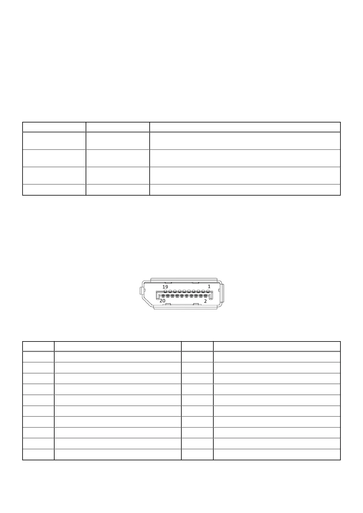
DisplayPort connectors
Two DisplayPort connectors on the front panel can connect to VGA, DVI, HDMI, and DisplayPort monitors using a DisplayPort to
VGA adapter cable, DisplayPort to DVI adapter cable, or DisplayPort to HDMI adapter cable and DisplayPort cable.
Figure 7. DisplayPort connector pin locations
Table 6. DisplayPort pin definitions
Pin Signal Pin Signal
1 CN_DDPx0+ 11 GND
2 GND 12 CN_DDPx3–
3 CN_DDPx0– 13 CN_DDPx_AUX_SEL
4 CN_DDPx1+ 14 CN_DDPx_CONFIG2
5 GND 15 CN_DDPx_AUX+
6 CN_DDPx1– 16 GND
7 CN_DDPx2+ 17 CN_DDPx_AUX–
8 GND 18 CN_DDPx_HPD
9 CN_DDPx2– 19 GND
10 CN_DDPx3+ 20 +V3.3_DDPx_PWR_CN
14 System Layout

 Loading...