Digital I/O connector
The EGW-5200 provides eight channels of non-isolation digital input and eight channels of non-isolation digital output circuits,
with specifications and circuits as follows.
● 8-channel digital input
○ VIH: 2 V to 5.25 V
○ VIL: 0 V to 0.8 V
● 8-channel digital output
○ Output type: Open drain N-channel
○ MOSFET driver with internal pull high of 200 Ω resistance
○ Source/sink current for all channels: 24 mA
○ VOH: 2.4 V to 5 V
○ VOL: 0 V to 0.5 V
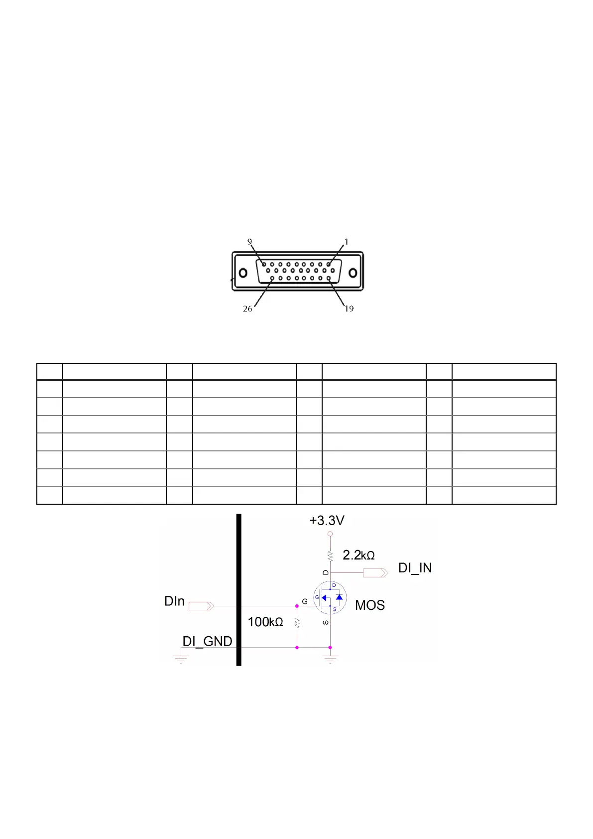
Figure 8. Digital I/O connector pin locations
Table 7. Digital I/O connector pin definitions
Pin Signal Pin Signal Pin Signal Pin Signal
1 DI0 8 DI7 15 N/C 22 DO3
2 DI1 9 GND 16 N/C 23 DO4
3 DI2 10 N/C 17 N/C 24 DO5
4 DI3 11 N/C 18 GND 25 DO6
5 DI4 12 N/C 19 DO0 26 DO7
6 DI5 13 N/C 20 DO1 - -
7 DI6 14 N/C 21 DO2 - -
Figure 9. Digital input circuit
System Layout
15
 Loading...