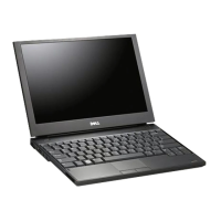
20. Lift the right side of the system board, and lift the board (with heat sink assembly and left I/O board) up at an angle to remove it from the base
assembly.
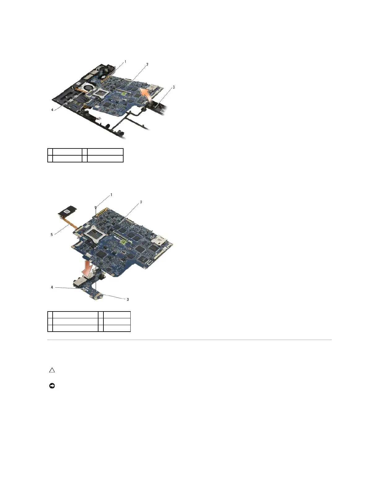
21. Remove the M2 x 3-mm screw securing the left I/O board to the system board.
22. Disconnect the left I/O board from the system board by pulling the two boards apart, separating the connectors.
Replacing the System Board Assembly
1. Connect the connector on the left I/O board to the connector on the system board.
2. Replace the M2 x 3-mm screw to secure the left I/O board to the system board.
3. Lower the left edge of the left I/O board into the left side of the base assembly, aligning the connectors with their corresponding holes in the base
assembly.
4. Lower the system board (with heat sink assembly and left I/O board) onto the alignment pins in the base assembly.
CAUTION: Before working inside your computer, read the safety information that shipped with your computer. For additional safety best
practices information, see the Regulatory Compliance Homepage on www.dell.com at: www.dell.com/regulatory_compliance.