The system memory contains 96 memory sockets organized into eight memory risers, split into four sets of two risers per processor. Each
memory riser has:
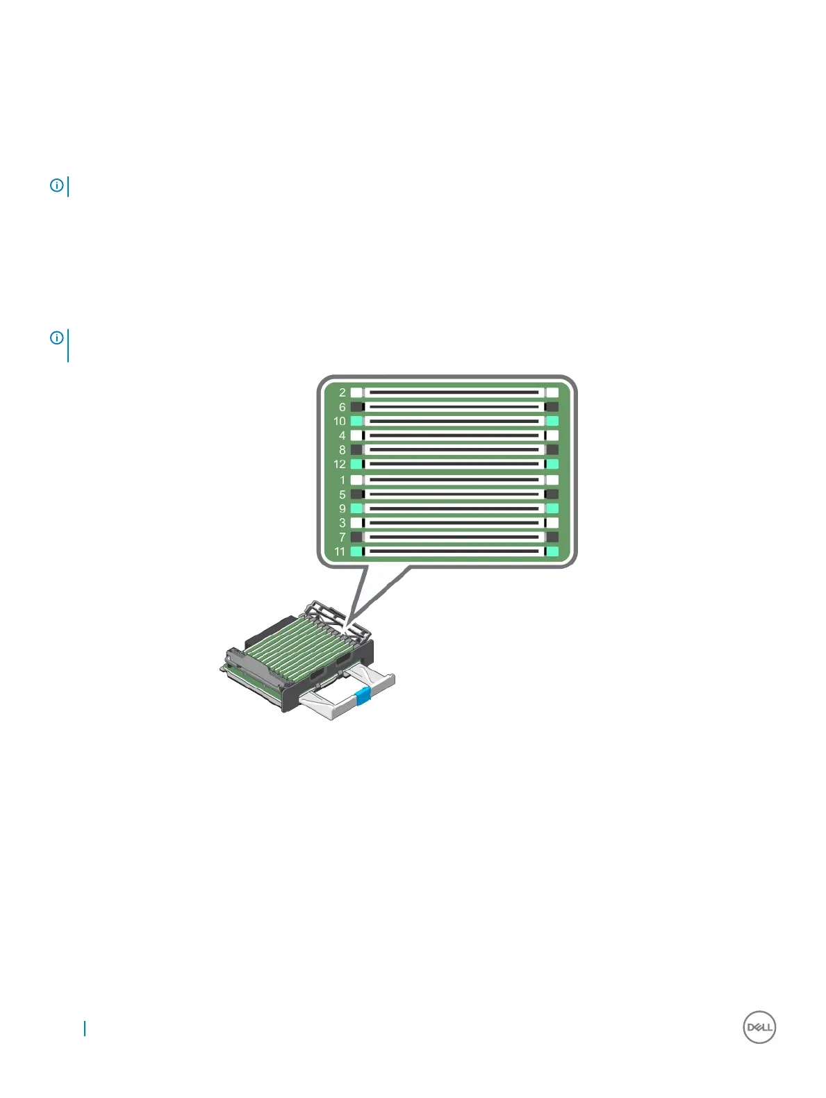
• 12 DIMM sockets arranged into four channels. In each channel, the release levers of the rst socket are marked white, the second
socket black, and the third socket green.
• Two Scalable Memory Interconnect-2 (SMI-2) ports that help DIMMs to connect with the processor.
• Two Scalable Memory Buers (SMB) that provide access to the DIMMs.
NOTE: GT/s indicates memory bus speed in GigaTransfers per second.
SMI-2 ports operate in two modes:
• Performance Mode (2:1) up to 3.2 GT/s for higher bandwidth
• Lock Step Mode (1:1) up to 1.87 GT/s for higher DDR4 speeds and better RAS (Reliability, Availability, and Serviceability) features
The maximum memory that is supported on your system varies according to the sizes of memory modules being used. Single, dual, and
quad rank DIMMs of capacities 8 GB, 16 GB, and 32 GB are supported for a total of up to 3 TB.
NOTE: DIMMs in memory risers A and B are assigned to processor 1, C and D are assigned to processor 2, E and F are assigned
to processor 3 and G and H are assigned to processor 4.
Figure 17. Memory socket locations
Memory channels are organized as follows:
Table 32. Memory channel organization
Processor
1
channel 0:
slots A1, A5,
and A9
channel 1:
slots A2, A6,
and A10
channel 2:
slots A3, A7,
and A11
channel 3:
slots A4, A8,
and A12
channel 0:
slots B1, B5,
and B9
channel 1:
slots B2, B6,
and B10
channel 2:
slots B3, B7,
and B11
channel 3:
slots B4, B8,
and B12
Processor
2
channel 0:
slots C1, C5,
and C9
channel 1:
slots C2, C6,
and C10
channel 2:
slots C3, B7,
and C11
channel 3:
slots C4, C8,
and C12
channel 0:
slots D1, D5,
and D9
channel 1:
slots D2, D6,
and D10
channel 2:
slots D3, D7,
and D11
channel 3:
slots D4, D8,
and D12
66 Installing and removing system components