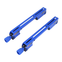
1. Assemble Stand Part 2
PC12
through Stand Part 1
PC11
that
has the cross support as shown in Figure 1.
ASSEMBLY
When lifting saw, hold it close to your body. KEEP knees bent and lift with your legs, not your back. Fully assemble Saw
with Stand Assembly prior to use. Stand Assembly is an integral and necessary part of the support structure for this Saw. DO NOT attempt
to substitute a table or other surface for the Stand Assembly. DO NOT modify saw, or create accessories not recommended for use with
this Saw. DO NOT connect to power supply until assembly is complete. Make sure power switch is in “OFF” position before connecting to
power supply. Avoid contact with Blade Teeth. KEEP Blade stored or lowered when possible.
Note: Stand only applicable for 36-6013 X models. 36-6013 models
see page 15.
FIGURE 4
FIGURE 2
CORRECT
HOLES FACING UP
INCORRECT
FIGURE 3
HP9
FIGURE 1
HP5
HP1
HP5
HP4
HP3
HP2
HP2
2. Using the supplied 4mm Combination Allen Wrench
HP9
and 13mm Combination Wrench (Not Supplied), secure
Stand Assembly with M8 x 65mm Hex Socket Head Screw
HP4
, M8 Plastic Spacer
HP3
, 2 Flat Washer 8mm x 14mm x
1.5T
HP2
, and M8 Lock Nut
HP5
. See Figure 2. Repeat this
for other side.
3. All four holes should face up to mount saw body. See
Figure 3 for correct stand parts setup.
NOTE: M8 Plastic Spacer
HP3
is between Stand Part 1
PC11
and
Stand Part 2
PC12
.
4. Turn stand upside down to attach legs. With assembled
stand open, with the 13mm Combination Wrench (Not
Supplied), attach (4) Stand Legs
PC13
to the stand using (8)
M8 x 30mm (1 3/16 inch) Carriage Bolts
HP1
and (8) M8
lock nuts
HP5
. Tighten lock nuts to secure legs to stand, as
seen in Figure 4.
NOTE: DO NOT over tighten lock nuts.
See nished assembly of stand in Figure 4.
ASSEMBLING THE STAND
PC13
PC12
PC12
PC12
PC11
PC11
PC11
13
 Loading...