ASSEMBLY
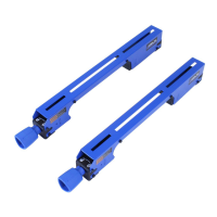
FIGURE 13
ANTI-KICKBACK PAWLS
To reduce the risk of serious personal injury,
Anti-Kickback Pawls
PC6
MUST be in place when making a
through cut.
1. Refer to Figure 13 and locate the Anti-Kickback Pawls
PC6
Mounting Slot in the middle of the top edge of the Riving
Knife
A
.
2. Slide slot in the middle of the Anti-Kickback Pawls
Assembly
PC6
along the top of the Riving Knife
A
until
the Press Pin
B
locates the center slot on the Riving
Knife
A
.
3. Depress the Press Pin
B
on the Anti-Kickback Pawls
Assembly
PC6
to allow the Assembly to drop into the slot.
Push down on the Anti-Kickback Pawls Assembly
PC6
until
it snaps into place and locks. Release Push Pin
B
.
NOTE: Pull up on the Anti-Kickback Pawls
PC6
to make sure it is
locked in place.
4. To remove the Anti-Kickback Pawls
PC6
, depress the Press
Pin
B
and pull the Anti-Kickback Pawls Assembly
PC6
o
the Riving Knife
A
.
FIGURE 15
PC6
A
B
FIGURE 14
BLADE GUARD
To reduce the risk of serious personal injury, the
Blade Guard MUST be in place when making a through cut.
1. Before installing the Blade Guard Assembly, make sure the
riving knife is raised to the thru-cut position. While holding
the Blade Guard Assembly
PC5
in a vertical position, hook
the Locating Pin
C
at the back end of the Blade Guard
Assembly into the slot at the back edge of the Riving Knife.
See Figure 14.
2. Rotate the Blade Guard Assembly toward the front of the
Saw until the Support Arms
D
of the Blade Guard
Assembly are parallel to the Table see Figure 15.
3. See Figure 16 (next page). While holding down on the
front of the support arms
B
of the Guard press the Blade
Guard Lock Tab
A
down until it snaps into the locked
position. Check to make sure the Guard is locked onto the
Riving Knife by pulling on the Guard. If the Guard is not
locked, the Blade Guard Lock Tab
A
will ip up to the
unlocked position.
If the Support Arm
D
of the Blade Guard
Assembly is not parallel to the Table, the Riving Knife is not in the
raised (through cut) position. Remove Blade Guard Assembly and
Anti-Kickback pawls and raise Riving Knife, then reinstall the Anti-
Kickback pawls and the Blade Guard Assembly.
4. Raise and lower each side of the Blade Guard to verify free
movement of the Guard System. Be sure the Guard System
can be raised enough to clear your workpiece.
NOTE: Blade alignment with Riving Knife can be adjusted. See:
“RIVING KNIFE POSITION AND ALIGNMENT”, page 27. Check the
Blade Guard for clearances and free movement.
D
PC5
C
ANTI-KICKBACK PAWLS AND BLADE GUARD
17
 Loading...