AH Motion – Hardware Manual
3-94
2 ERROR LED indicator
Error status of the module
ON: A serious error occurs in the module.
OFF: The module is normal.
Blink: A slight error occurs in the module.
The inputs are connected to a sensor.
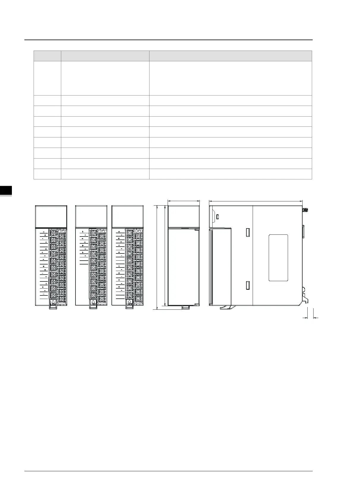
Arrangement of the input terminals
Arrangement of the terminals
5 Description of the inputs Simple specifications for the module
Removing the terminal block
Connecting the module and a backplane
Dimensions:
110
114
35
6
103
I1
O1
O0
I3
O3
I0
RUN
ERROR
O2
I2
I0
FG
I1
04PT
O0
FG
O1
I3
I2
FG
O2
FG
RTD
2/3/4-WIRE
O3
I3
FG
FG
I3
Thermocouple
J,K,R,S, T,E,N
I2
I2
I1
I1
I0
I0
08TC
RUN
ERROR
I6
I5
I5
I4
I7
FG
I7
I6
FG
I4
I0
I0
04TC
I3
FG
FG
I3
RUN
ERROR
I2
I2
I1
I1
Thermocouple
J,K,R,S, T,E,N
Dimensions are in mm.
 Loading...


