Chapter 7 Optional AccessoriesC2000
7-4
Table 7-4
Table 7-5
Applicable
Motor (kW)
*
1
125% Braking Torque / 10%ED *
2
Max. Braking Torque
LD ND HD
Braking
Torque
[kg-m]
Brake
Unit
VFDB
*
3
Braking Resistor series for
each Brake Unit
Resistor value
spec. for each
AC motor drive
Total
Braking
Current
[A]
Min.
Resistor
Value
[Ω]
Max.
Total
Braking
Current
[A]
Peak
Power
[kW]
450 355 315 240.3 6200*2 BR1K5W027*14
2 series,
7 parallel
42000W 3.9Ω 290.4 3.5 324 362.9
560 450 355 304.7 6200*3 BR1K5W027*12
2 series,
6 parallel
54000W 3.0Ω 373.3 2.3 486 544.3
630 630 630 426.5 6200*4 BR1K5W027*12
2 series,
6 parallel
72000W 2.3Ω 497.8 1.7 648 725.8
*1.
Calculation for 125% brake toque: (kW) * 125% * 0.8; where 0.8 is motor efficiency.
Because of the limited resistor power, the longest operation time for 10% ED is 10 seconds (on: 10 seconds / off: 90 seconds).
*2.
Refer to Chapter 7 “Brake Module and Brake Resistors” in application manual for “Operation Duration & ED” vs. “Braking
Current”.
*3.
For heat dissipation, a resistor of 400W or lower should be fixed to the frame and maintain the surface temperature below
250°C; a resistor of 1000W and above should maintain the surface temperature below 350°C.
*4.
Please refer to VFDB series Braking Module Instruction for more detail on braking resistor.
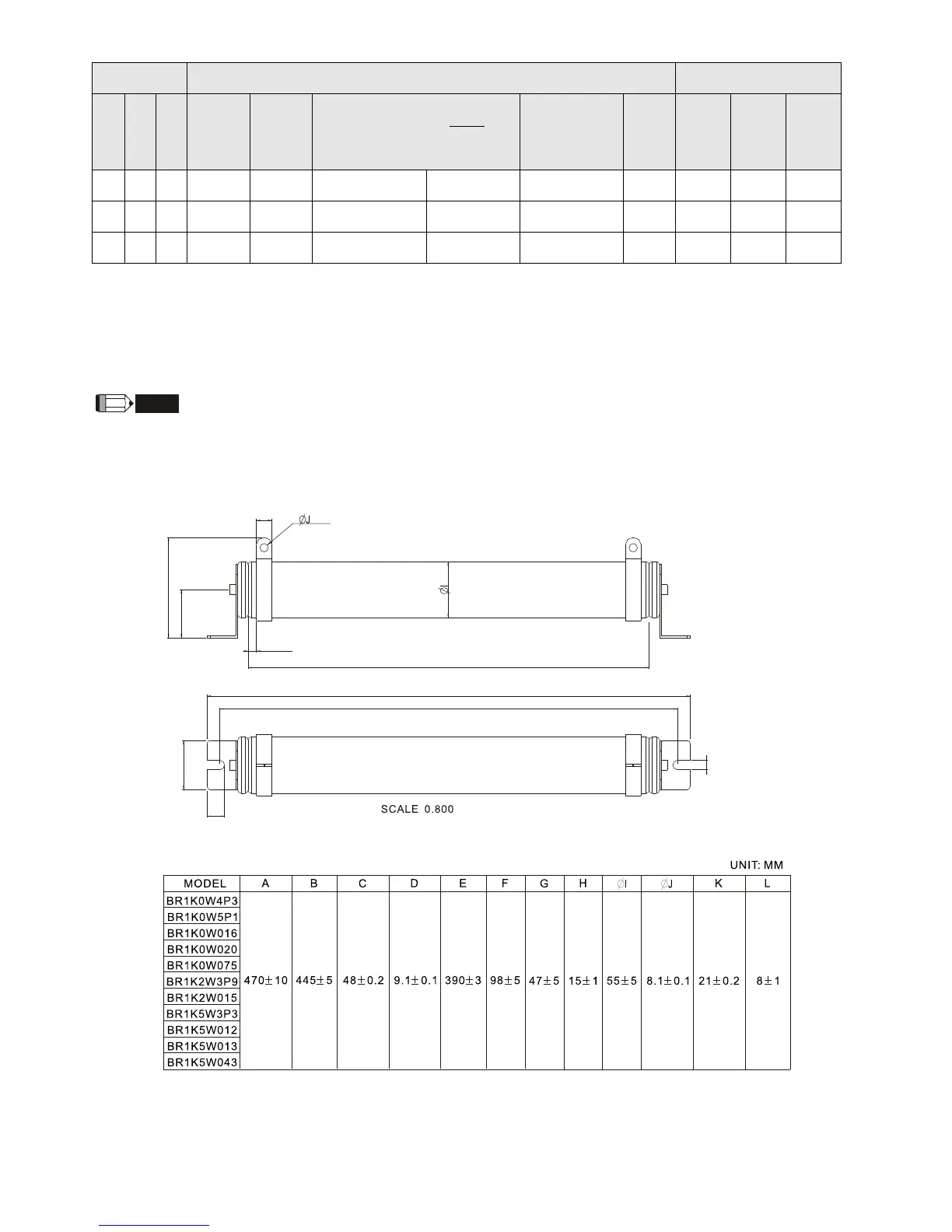
NOTE
1. Specification and appearance of brake resistors
1-1 Wirewound resistor: for 1000W and above. Refer to the following appearance of wirewound resistor
(Figure7-1) and its model and specification comparison table (Table 7-5) for details.
A
B
C
D
H
F
K
G
E
L
Figure 7-1