Chapter 7 Optional AccessoriesC2000
7-101
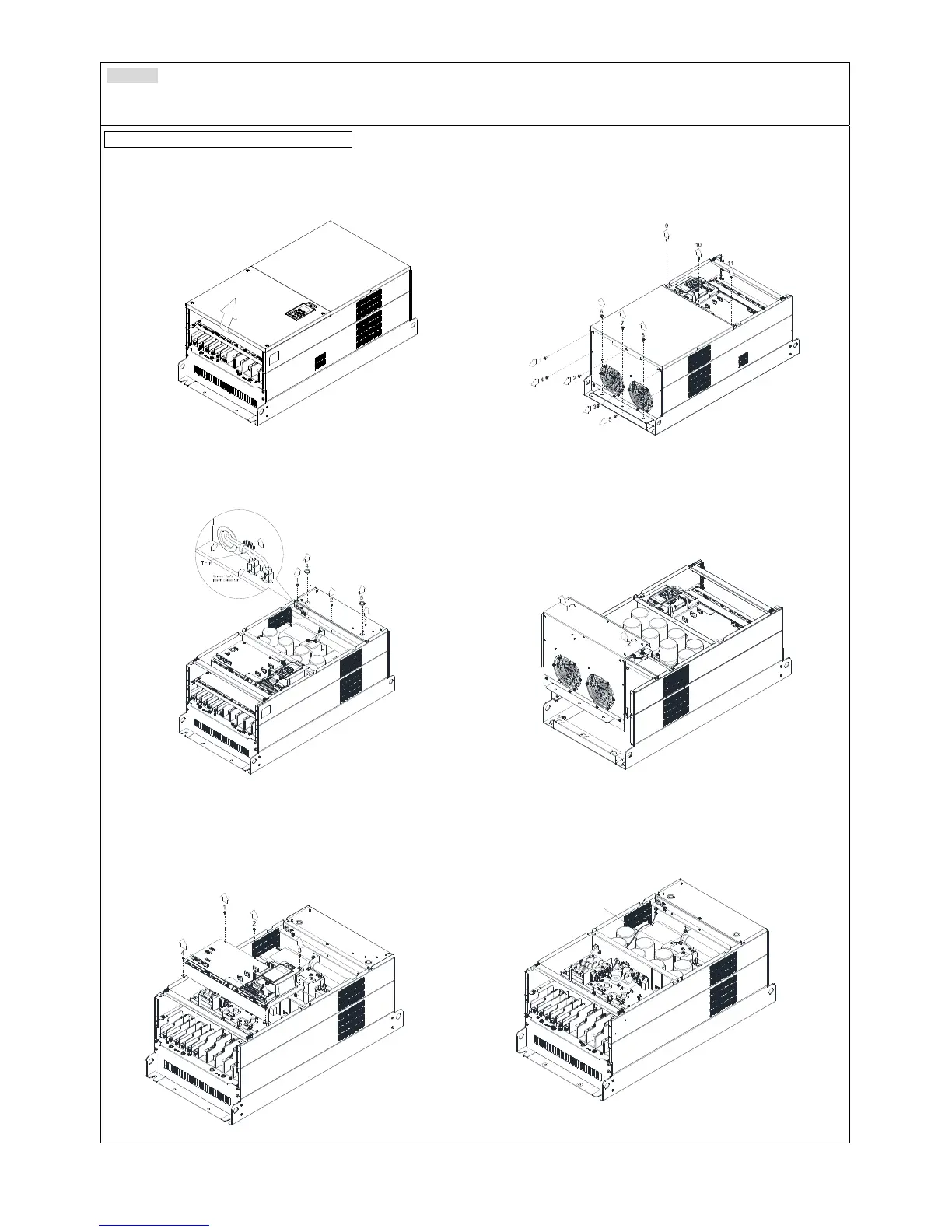
Frame G
Applicable model
VFD1850C43A/43E; VFD2200C43A/43; VFD2500C63B-00; VFD3150C63B-00; VFD2500C63B-21; VFD3150C63B-21
Fan model “MKC-GFKM” Heat Sink Fan
1. Loosen the screw (figure 1) and remove the cover.
Screw torque: 12~15 kg-cm / [10.4~13.1 Ib-in.] /
[1.2~1.5 Nm]
1
4
2
3
Figure 1
2. For 1~8 shown in the figure 2: Loosen the screws
Screw torque: 35~40 kg-cm / [30.4~34.7 Ib-in.] /
[3.4~3.9 Nm]
3. For 9~11 shown in the figure 2: Loosen the screws and
removes the cover. Screw M4 torque:
14~16 kg-cm /
[12.2~13.9 Ib-in.] / [1.4~1.6 Nm]
Figure 2
4. Loosen screw 1, 2, 3 and remove the protective ring (as
shown in figure 3) Screw torque: 14~16 kg-cm / [12.2~13.9
Ib-in.] / [1.4~1.6 Nm]
Figure 3
5. Lift the fan by putting your finger through the protective
holes, as indicates in 1 and 2 on the figure 4.
Figure 4
6. For old drivers switching new fans, please follow below
steps:
Loosen screws 1~5, remove the cover (as below figure
shown) M4 screw torque: 14~16 kg-cm / [12.2~13.9 lb-in] /
[1.4~1.6 Nm]
Figure 5
7. Add cable model 3864483201 to connect the power board
and fan connector. (The cable 3864483201 goes with the
fan as accessory)
Figure 6
Cable 3864483201