VFD-V Series
DELTA ELECTRONICS, INC. ALL RIGHTS RESERVED
8-10
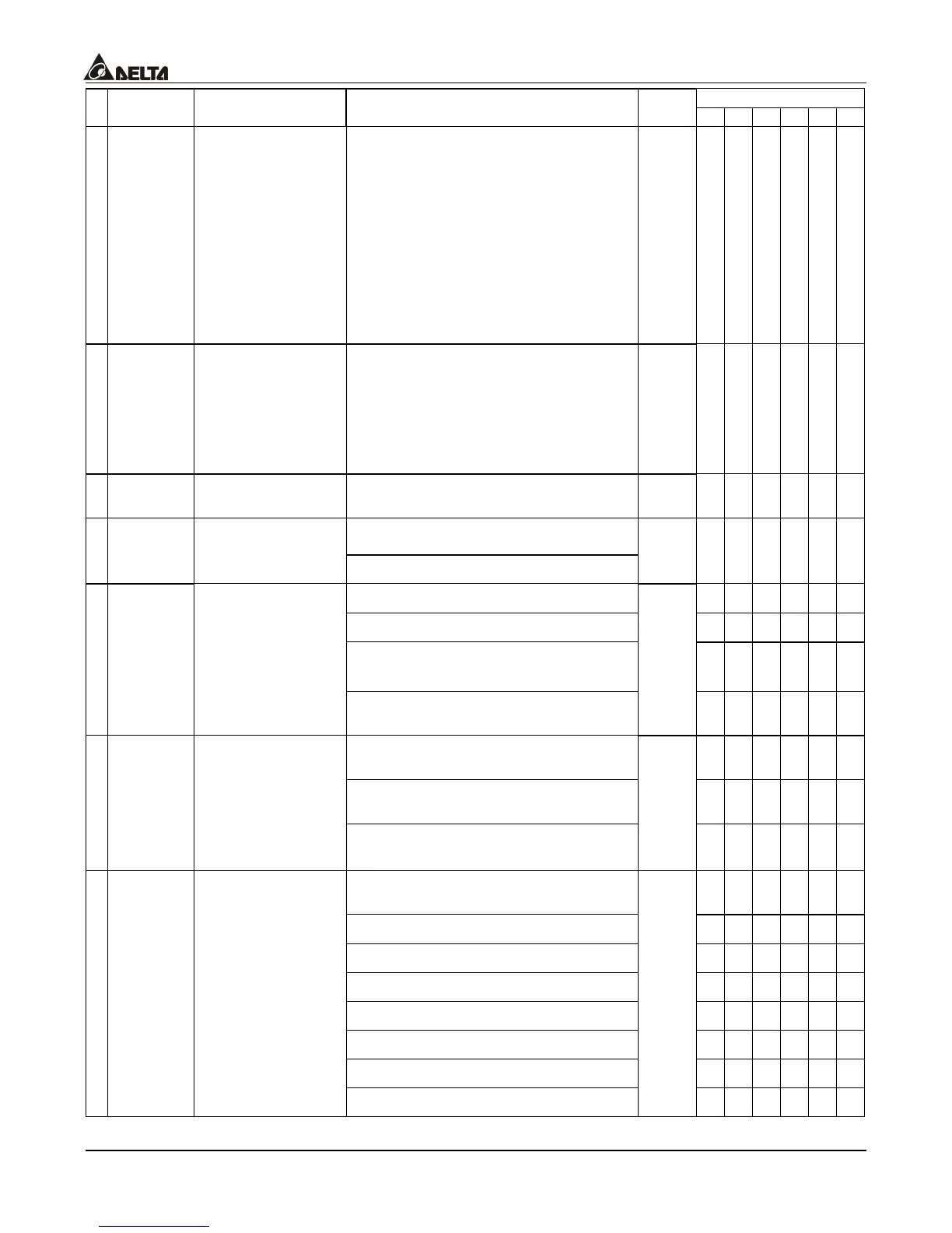
Control Mode
Parameters Functions Settings
Factory
Setting
VF VG SV SG T TG
a
02-07
UP/DOWN key
mode
Bit 0=0: UP/DOWM following the
acceleration/deceleration time
Bit 0=1: UP following the constant
speed, and DOWN following the
deceleration time
Bit 1=0: UP following the
acceleration time, and DOWN
following the constant speed
Bit 1=1: UP/DOWN following the
constant speed
00000
{ { { { { {
a
02-08
The Acceleration
/Deceleration
Speed of the
UP/DOWN Key
with Constant
Speed
0.01~1.00Hz/msec 0.01
{ { { { { {
a
02-09
Digital Input
Responding Time
0.001~30.000 Sec
0.005
{ { { { { {
0~65535
a
02-10
Digital Input
Operation
Direction
Bit 0~7=1 high active
0
{ { { { { {
0: no function
{ { { { { {
1: AC drive running
{ { { { { {
2: operation speed attained 1 (both
directions)
{ { { { ° °
a
02-11
Multi-Function
Output 1 RA,
RB, RC (Relay 1)
3: operation speed attained 2 (both
directions)
15
{ { { { ° °
4: pre-set speed attained 1 (both
directions)
{ { { { { {
5: pre-set speed attained 2
(forward only)
{ { { { { {
a
02-12
Multi-Function
Output 2 MRA,
MRC (Relay 2)
6: pre-set speed attained 1 (both
directions)
1
{ { { { { {
7: pre-set speed attained 2
(forward direction)
{ { { { { {
10: zero speed
{ { { { { {
11: over-torque(oL2)
{ { { { { {
12: base block (Pause)
{ { { { { {
13: drive ready for use
{ { { { { {
14: low voltage alarm (LV)
{ { { { { {
15: error indication
{ { { { { {
a
02-13
Multi-Function
Output 3 MO1
16: drive operation mode
2
{ { { { { {

 Loading...

