- 19 -
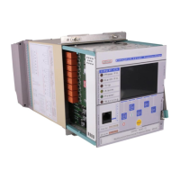
CPM 310 G: Internal Unit – Rear & Left Side View
Internal Unit Terminal Sockets
Sockets make the electrical connection by locking to the plugs when the internal unit is drawn into the
case. All sockets are made of inflammable material.
Internal Unit Tracks
High-endurance internal unit tracks provide robust draw-in and draw-out operation of the internal unit.
Faraday Cage
Digital signal processors, microprocessors and other critical components are safely embedded within the
Faraday cage, clear of wave or field effects that may risk the performance of the relay.
Fuse Holder
The T1A fuse protecting the internal circuit is mounted on this fuse holder. The fuse ensures the protection
of the internal circuits in case of any auxiliary supply faults and provides maximum service continuity. The
placement of the fuse holder enables quick access and fast replacement of the fuse.
Real-time-clock Battery
Real-time clock is run by the auxiliary supply power while the relay is in service; in case of auxiliary supply
shortage or internal unit drive out, real-time clock battery takes the duty over. Life expectancy of the
lithium-ion battery is 10 years under normal conditions. The unit can be replaced by removing the
protecting plastic cover.
 Loading...