Technical Characteristics
Used for increasing trip delays for the selected protection functions while the
protection group is set to "1".
Start Wave Record Used for triggering a 3 second record of the current waveform.
Used for increasing the threshold settings of the selected protection function for a
given time.
Spring Failure Supervises the CB charging spring via auxiliary contacts.
Change Set.Group Used for altering between protection settings groups 1 and 2.
Block ARCL Used for disabling auto-reclose cycles.
Reset %Θ Used for resetting the thermal image.
Trip Circuit Sup. Supervises the trip circuit of circuit breaker.
Reset RL1-RL6 Resets all programmable outputs.
Reset LED Used for resetting programmable LEDs and alarm records.
Pressure Trip Evaluates the pressure trip auxiliary contact information.
Buchholz Alarm Evaluates the Buchholz alarm auxiliary contact information.
Buchholz Trip Evaluates the Buchholz trip auxiliary contact information.
Temp.Alarm Evaluates the thermometer alarm auxiliary contact information.
Temp.Trip Evaluates the thermometer trip auxiliary contact information.
Used for blocking selected protection functions while the protection group is set to
"2".
Used for increasing trip delays for the selected protection functions while the
protection group is set to "2".
Connection Cable 2-wire screened communications cable.
4 terminals at the rear side of the device: reference, sending, receiving and
termination resistance terminals.
Communications Protocols DEMCOM (DEMA communications protocol), MODBUS and IEC60870-5-103.
Communications Speed min. 1,200 baud, max. 38,400 baud.
Insulation Level 2000 V / 1 min.
Connection Type Between CPM 310 G and PC.
USB serial port is used for establishing communications between CPM 310 G and a
PC for using DEMA DigiConnect software.
Connection Point On the front side of the relay, USB B-type connector under the cover.
Communications Protocols DEMCOM (DEMA communications protocol) and MODBUS.
Communications Speed min. 1,200 baud, max. 38,400 baud.
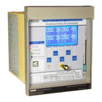
S1, S2, S3, S4, S5 Buttons Multifunctional buttons, functioning as described on the screen for each menu.
Reset button has cyclic duty over LED, Alarm and Ampermeter menus. While at
any menu; first hit heads to the "Programmable LEDs" menu, second hit heads to
the "Alarm Menu" if any alarms are available, or to the "Ampermeters" menu if
there are no alarms to display. Hitting further returns to the initial menu. The reset
button is reachable either the cover is closed or open.
1.7 Command Interface Buttons
1.6 USB Serial Communications Port
1.5 RS485 Serial Communications Port
Programmable Input Setting Options (Continued)
 Loading...