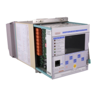
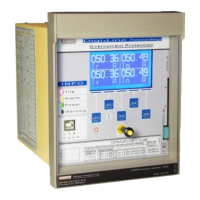
Technical Characteristics
Pick-up Current For all threshold values: over 1.05 times the set value.
Current Reset Ratio (Hysteresis) ~%95
Instantaneous Trip Time ~35 ms
Trip Time Delays for Earth Thresholds
Tripping delay ranges for earth fault protection is the same with those for phase
fault protection. DMT and IDMT characteristics available.
Reset Time Delays for Earth Thresholds
Reset delay ranges for earth fault protection is the same with those for phase fault
protection. DMT and IDMT characteristics available.
Measurement Technique RMS current.
Threshold Setting Range
IΘ> = (0.1-3.2) I
n
, in steps of 0.01 I
n
.
Thermal Constant Setting Range
T
e
: (1-200) min, in steps of 1 min.
Thermal Trip Level Multiplier (k) Setting
Range
k : 1-1.5, in steps of 0.01.
Thermal Trip Level Setting Range Trip Θ : %(50-200), in steps of: %1.
Thermal Alarm Level Setting Range Alarm Θ : %(50-200), in steps of: %1.
%(I
2
/I
1
)> where I
1
is fundamental harmonics of positive sequence and I
2
is
fundamental harmonics of negative sequence current.
%(I
2
/I
1
)> Setting Range
%(20-100), in steps of %1.
Tripping Delay Setting Range (1-14,400) s, in steps of 1 s.
Measurement Technique Fundamental harmonic.
Threshold Setting Range
(0.1-40) I
n
There are 2 independent thresholds available for negative sequence overcurrent
protection function.
I
2
> = (0.1-40) I
n
, in steps of 0.01 I
n.
I
2
>> = (0.1-40) I
n
, in steps of 0.01 I
n.
Current Reset Ratio (Hysteresis) ~%95
Tripping Delay Setting Range The range is the same with phase overcurrent protections'.
Resetting Delay Setting Range The range is the same with phase overcurrent protections'.
Measurement Technique Fundamental harmonic.
Threshold Setting Range
I< = (0.02-1.0) I
n
, in steps of 0.01 I
n.
Tripping Delay Setting Range tI< = (0.01-150) s, in steps of 0.01 s.
Triggering Condition Current measurement below the set level while 52a input is active.
Current Reset Ratio (Hysteresis) ~ %105
2.6 Undercurrent Protection (I<) [ANSI 37]
2.2 Earth Overcurrent Protection [ANSI 50N/51N] (Continued)
2.3 Thermal Overload Protection [ANSI 49]
2.4 Broken Conductor Detection [%(I2/I1)>]
2.5 Negative Sequence Overcurrent Protection (I2>) [ANSI 46]
Thresholds and Setting Ranges
 Loading...