- 41 -
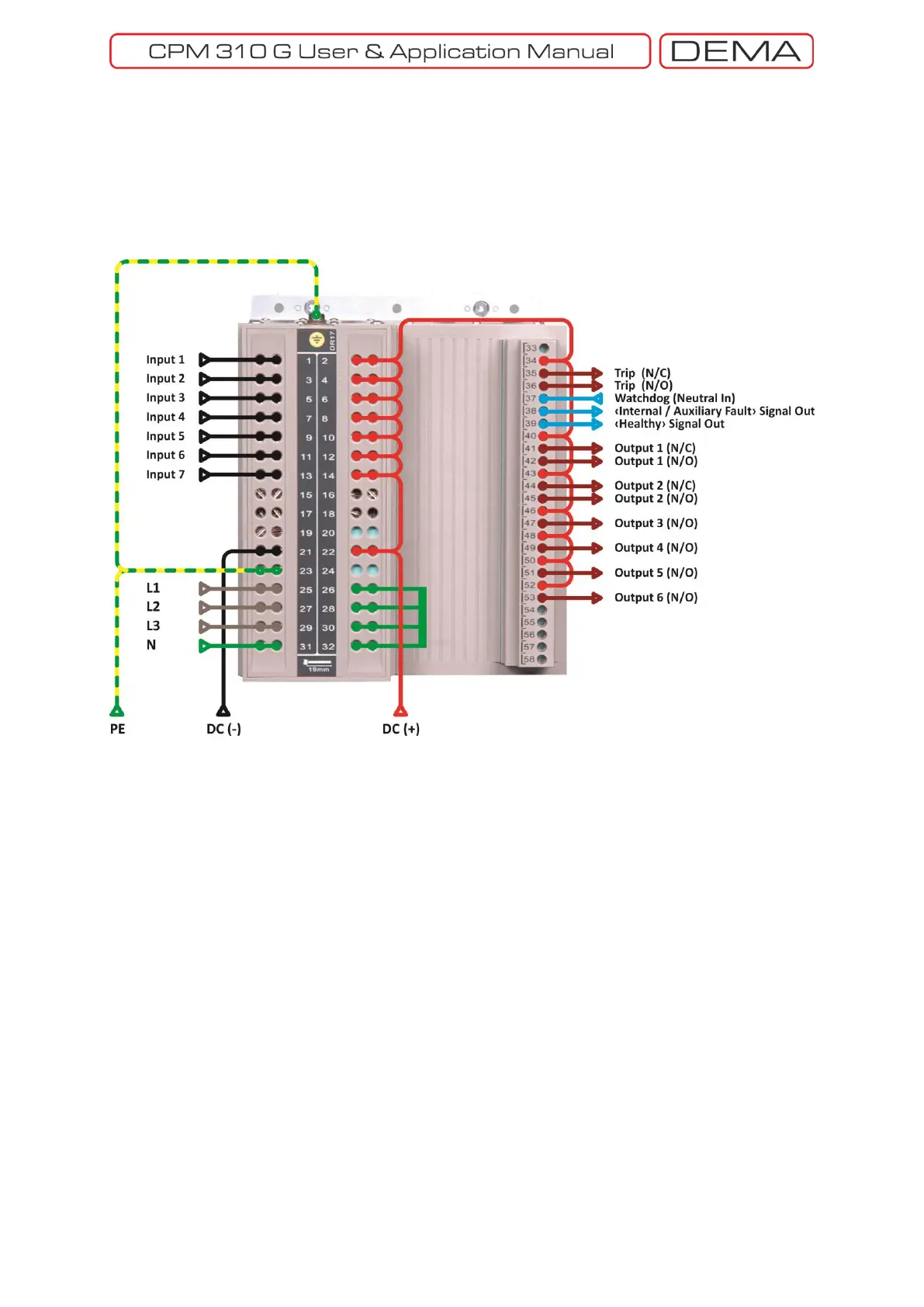
DEMA CPM 310 Sample cabling diagram is given below. The cabling color codes are given on the top
right corner; according to the coding logic, DC (+) cables are in red, DC (-) are in black, AC (L or N)
supply cables are in blue, current transformer live secondary signal (L1, L2, L3) cables are in brown,
current transformer neutral point (N) cable is in yellow, and protective earthing (PE) cables are in
green. Sample diagram is created assuming that neutral point of secondary current lines is to be
earthed.
Sample CPM 310 G Cabling Diagram
As explained at the
CPM 310 G Terminal Explanations
list and shown on the diagram above, the
common supplies for input and outputs are done as DC (+), excluding Watchdog relay supply. This
wiring assumes the following conditions:
Inputs signals from external sources (e.g. a buchholz signal from a power transformer) would
be in DC (-) polarity,
Output signals to external devices (e.g. the trip coil of a circuit breaker) would be of DC (+)
polarity.
If your actual circuit has different polarity requirements, prepare your cabling diagram accordingly.
It is seen on the diagram that the watchdog output is supplied with AC. The logic for this application
is, that systems with DC auxiliary supply needs another auxiliary supply source, so that an alarm
signal can be taken from the normally closed contact of the watchdog relay. If the circuit diagram
given in the former page is examined, it will be determined that the watchdog terminal 39 is closed to
37 in normal service conditions – if any auxiliary supply failure occurs, the relay will release and 38
terminals will be shorted to 37, allowing an alarm signal even when the relay is not functioning. It
must be noted that this principle works if the supply source of watchdog differs from the main
auxiliary supply of the relay. Similarly, a “System OK” signal can be taken out from the terminal no.39.

 Loading...