- 48 -
1. In order to make the settings of the dip-switches, access to the internal unit must be provided.
Drive out the internal unit.
2. Dip-switches are located in top right quadrant of the right side of the internal unit, when the unit
is viewed from the front (see p.20). Their descriptions are given below.
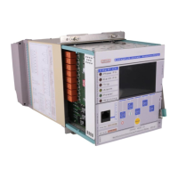
If a dip-switch is up, it is in “ON” position, if it is down, it is in “OFF” position. At the figure below,
all dip-switches are at “ON” position.
Dip-switches Top View
3. Once the determinations are done for current transformer characteristics and earth protection
type needed for the application, settings can be figured out as described below.
4. After completing the settings of the dip-switches, drive the internal unit into place and go to the
CT Settings
menu on the relay. Set the characteristics on the menu as are done on the dip-
switches. Doing this, dip-switch and CT settings are completed.
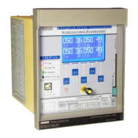
Setting Earth Nominal Current and Range
If the current transformer is of X / 5 A type, set as follows;
For T1 type (0.1 - 40) I
en
range: E1 “ON”, E2 “ON”
For T2 type (0.02 - 5) I
en
range: E1 “OFF”, E2 “ON”
If the current transformer is of X / 1 A type, set as follows;
For T1 type (0.1 - 40) I
en
range: E1 “OFF”, E2 “ON”
For T2 type (0.02 - 5) I
en
range: E1 “OFF”, E2 “OFF”
The figure on the right shows a setting example for a current
transformer set of X / 5 A and an earth fault protection range of
(0.1 - 40) I
en
.
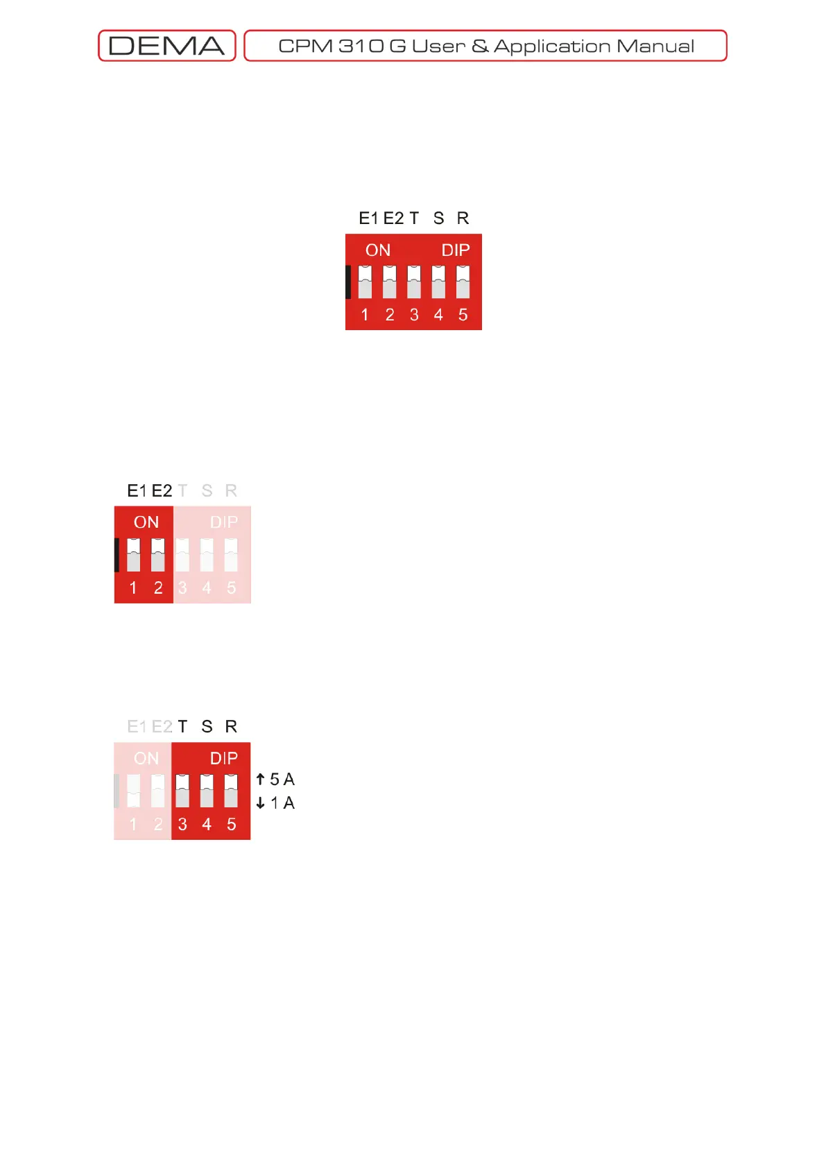
Setting Phase Nominal Current and Range
If the current transformer is of X / 5 A type, set as follows;
T, S, ve R dip-switches to “ON” position.
If the current transformer is of X / 1 A type, set as follows;
T, S, ve R dip-switches to “OFF” position.
The figure on the right shows a setting example for a current
transformer set of X / 5 A.
There are no options for phase overcurrent protection range;
the range is available only as (0.1 - 40) I
n
.
 Loading...