-LA-3500
28
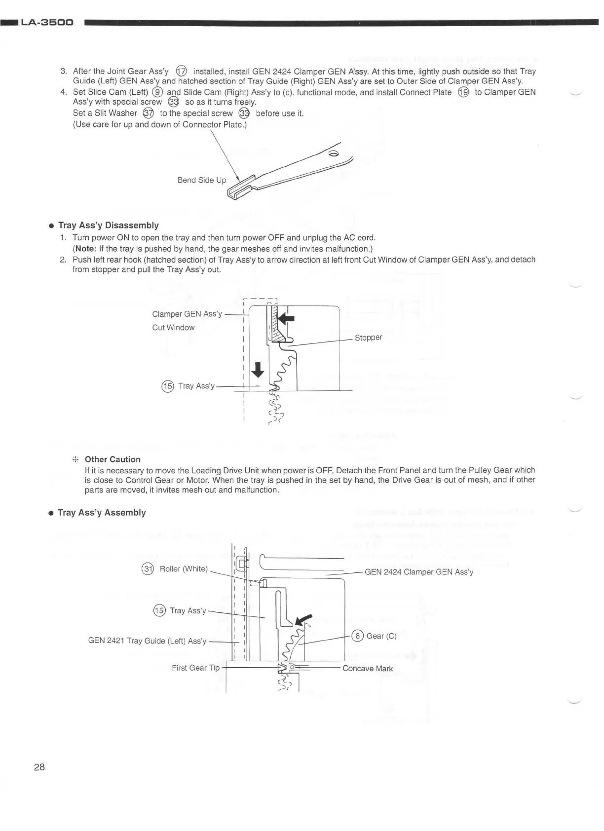
3.
After the Joint
Gear
Ass'y @ installed, install GEN 2424 Clamper GEN A'ssy. At this time, lightly push outside so that Tray
Guide (Left) GEN Ass'y and hatched section of Tray Guide (Right) GEN Ass'y are set to
Outer
Side of Clamper GEN Ass'y.
4.
Set Slide
Cam
(Left) ® and Slide Cam (Right) Ass'y to (c). functional mode, and install Connect Plate @ to Clamper GEN
Ass'y with
special screw @ so as it turns freely.
Set
a Slit Washer @ to the special screw ® before use it.
(Use care for up and down of Connector Plate.)
BoodS;d~
• Tray Ass'y Disassembly
1.
Turn power ON to open the tray and then turn power OFF and unplug the AC cord.
(Note:
If
the tray is pushed by hand, the gear meshes off and invites malfunction.)
2.
Push left rear hook (hatched section) of Tray Ass'y to arrow direction at left front Cut Window of Clamper GEN Ass'y, and detach
from stopper and
pull the Tray Ass'y out.
Clamper GEN Ass'y
Cut Window
Stopper
@ Tray
Ass
'y
--
_
-_>-
_
1-
1__
- -
-'.""""'----
- '---
----'---
...._~~
.,. Other Caution
r...C..-")
c~
,
r J<
If it is necessary to move the Loading Drive Unit when power is OFF, Detach the Front Panel and turn the Pulley
Gear
which
is
close
to
Control
Gear
or Motor. When the tray is pushed
in
the set by hand, the Drive
Gear
is out of mesh, and if other
parts are moved, it invites mesh out and
malfunction.
• Tray Ass'y Assembly
@ Roller (White)
=-
------
--
-
GEN
2424 Clamper
GEN
Ass
'y
@Tray
Ass
'y
GEN
2421
Tray Guide (Left)
Ass
'y
---n-
® Gear(C)