...................................................................................
LA-3500
..
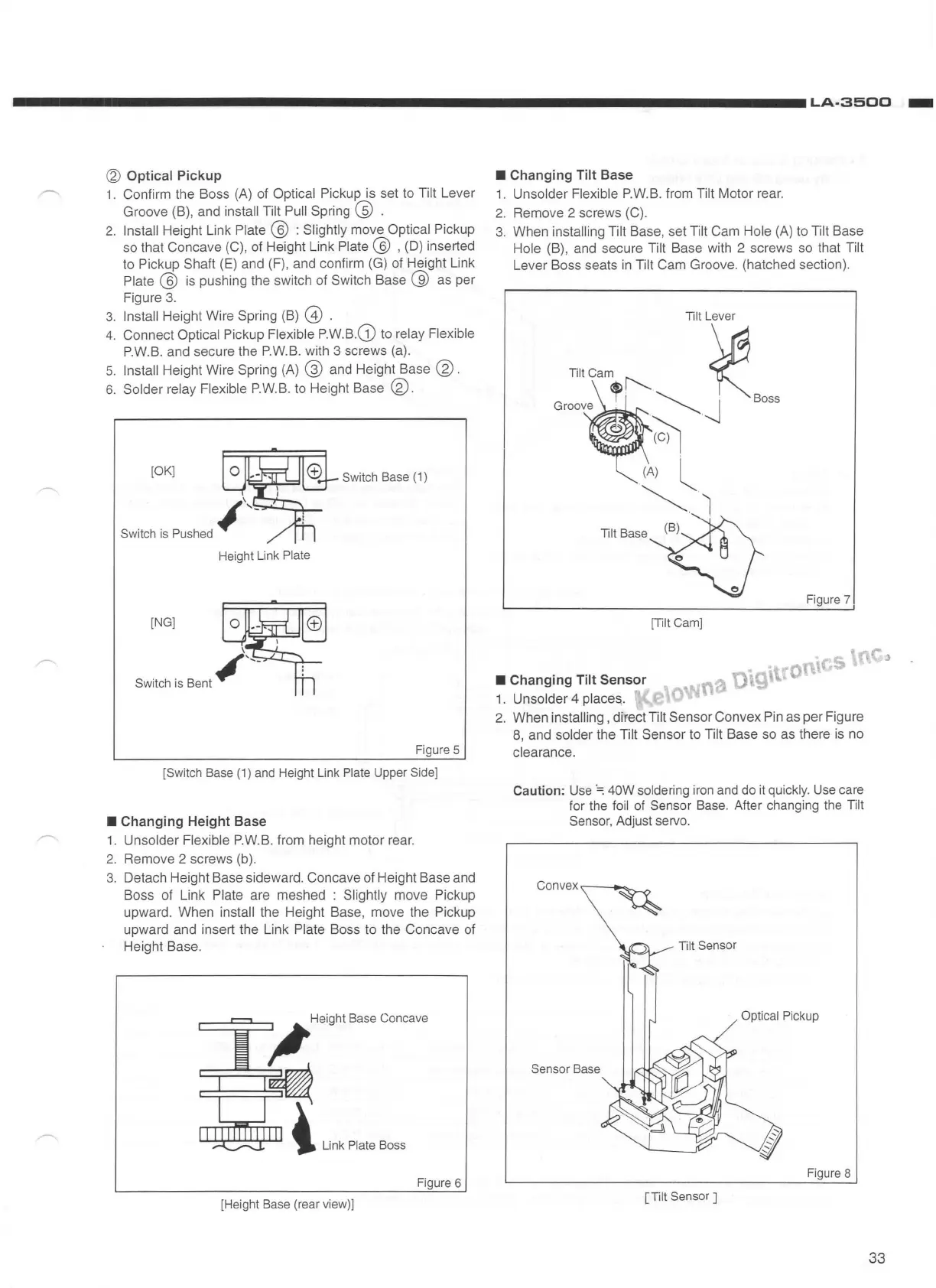
'2) Optical Pickup
1.
Confirm the Boss (A) of Optical Pickup is set to Tilt Lever
Groove (B), and
install Tilt Pull Spring @ .
2.
Install Height Link
Plate@
: Slightly move Optical Pickup
so that Concave (C), of Height Link
Plate @ , (D) inserted
to Pickup Shaft (E) and (F) , and confirm (G) of Height Link
Plate @
is
pushing the switch of Switch Base @ as per
Figure
3.
3.
Install Height Wire Spring (B) @ .
4.
Connect Optical Pickup Flexible
P.W.B
.G)
to relay Flexib
le
P
.W.
B.
and secure the P.W.B. with 3 screws (a).
5.
Install Height Wire Spring (A) @ and Height Base @.
6.
Solder relay Flexible P.
W.
B.
to Height Base ®.
[OK]
Switch
B
ase
(1)
Switch
is
Pushed
~',_
Height
Link
Plate
[NG]
\
Switch
is
Bent#'--
Figure
5
[Switch
Base
(1)
and
Height
Link
Plate
Upper
Side]
•Changing
Height Base
1.
Unsolder Flexible P.W.B. from height motor rear.
2.
Remove 2 screws (b).
3.
Detach Height Base sideward. Concave of Height Base and
Boss of Link
Plate are meshed : Slightly move Pickup
upward. When
install the Height Base, move the Pickup
upward and insert the Link
Plate Boss to the Concave of
Height Base.
Figure
6
[Height
Base
(rear
view)]
•Changing
Tilt Base
1. Unsolder Flexible P.W.B . from Tilt Motor rear.
2.
Remove 2 screws (C) .
3.
When installing Tilt Base, set Tilt Cam Hole (A) to Tilt Base
Hole (B), and secure Tilt Base with 2 screws so that Tilt
Lever Boss seats
in
Tilt Cam Groove. (hatched section) .
Tilt
Lever
Tiit
Cam !'--.
~
G
, .
'-.......
:
Boss
roove
'-.......
....,,j
........................
~
.
(A) l
~I
Tilt
Base
Figure
7
[Tilt
Cam]
·s
• Changing Tilt Sensor
1. Unsolder 4 places,.
2.
When installing , direct Tilt Sensor Convex Pin as per Figure
8, and
solder the Tilt Sensor to Tilt Base so as there is no
clearance.
Caution:
Use
·=:
40W soldering
iron
and
do
it
quickly.
Use
care
for the
foil
of
Sensor
Base
. After changing
the
Tilt
Sensor,
Adjust servo.
Tilt
Sensor
Optical
Pickup
Sensor
Base
Figure
8
[Tilt
Sensor
]
33