-LA-3500
40
2.
Grating
Caution:
Never turn grating adjustment
pin
too much . (Limits : ±
2-3
degree). Further turn disables
RF
signal detection and further
adjustment.
Test
Point Adjust
Mode
Disk
HF
Grating hole
Playback
TCD-725
TEO
pause
Track 1 O
lnsturment
Adjust
to
Oscilloscope
Refer
to
Below
1.
Place the unit on fixture, connect CH 1 of oscillos
cope
to
HF
and
CH2
to
TEO
.
2.
Playback track 1 O of CD test disk (
TCD-
725).
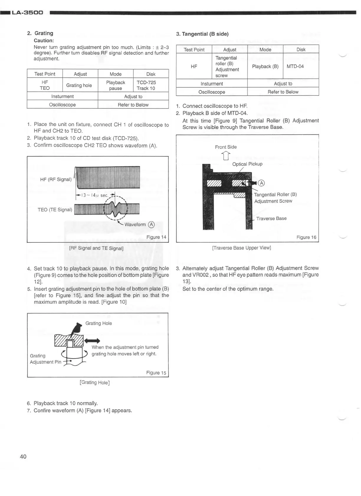
3. Confirm
oscilloscope CH2
TEO
shows waveform (A).
HF
(
RF
Signal)
TEO
(TE
Signal)
...........
__
.,,.,,
'-Waveform
@
Figure
14
[RF Signal
and
TE Signal]
4.
Set track 1
Oto
playback
pause
.
In
this mode, grating hole
(Figure 9)
comes
to
the hole position of bottom plate [Figure
12].
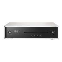
5.
Insert grating adjustment pin to
the
hole of bottom plate (B)
[refer to Figure 15], and fine adjust the pin so that the
maximum
amplitude is read. [Figure 1
OJ
Figure
15
[Grating Hole)
6.
Playback track 10 normally.
7.
Confire waveform (A) [Figure 14] appears.
3. Tangential
(8
side)
Test
Point Adjust
Mode
Dis
k
Tangential
HF
roller (
B)
Playback (B)
MTD-04
Adjustment
screw
lnsturment
Adjust
to
Oscilloscope
Refer
to
Below
1.
Connect oscilloscope
to
HF.
2.
Playback B side of
MTD-04
.
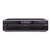
At this time [Figure
9]
Tangential Roller (B) Adjustment
Screw
is visible through the Traverse Base.
Front
Side
D
Tangential Roller
(B)
Adjustment
Screw
Tra
ve
rs
e
Base
[Traverse Base Upper
View]
Fi
gu
re
16
3. Alternately adjust Tangential Roller (B) Adjustment
Screw
and VR002 , so that
HF
eye pattern reads
maximum
[Figure
13].
Set
to the
center
of the optimum range.