..............................................................................
LA-3500
..
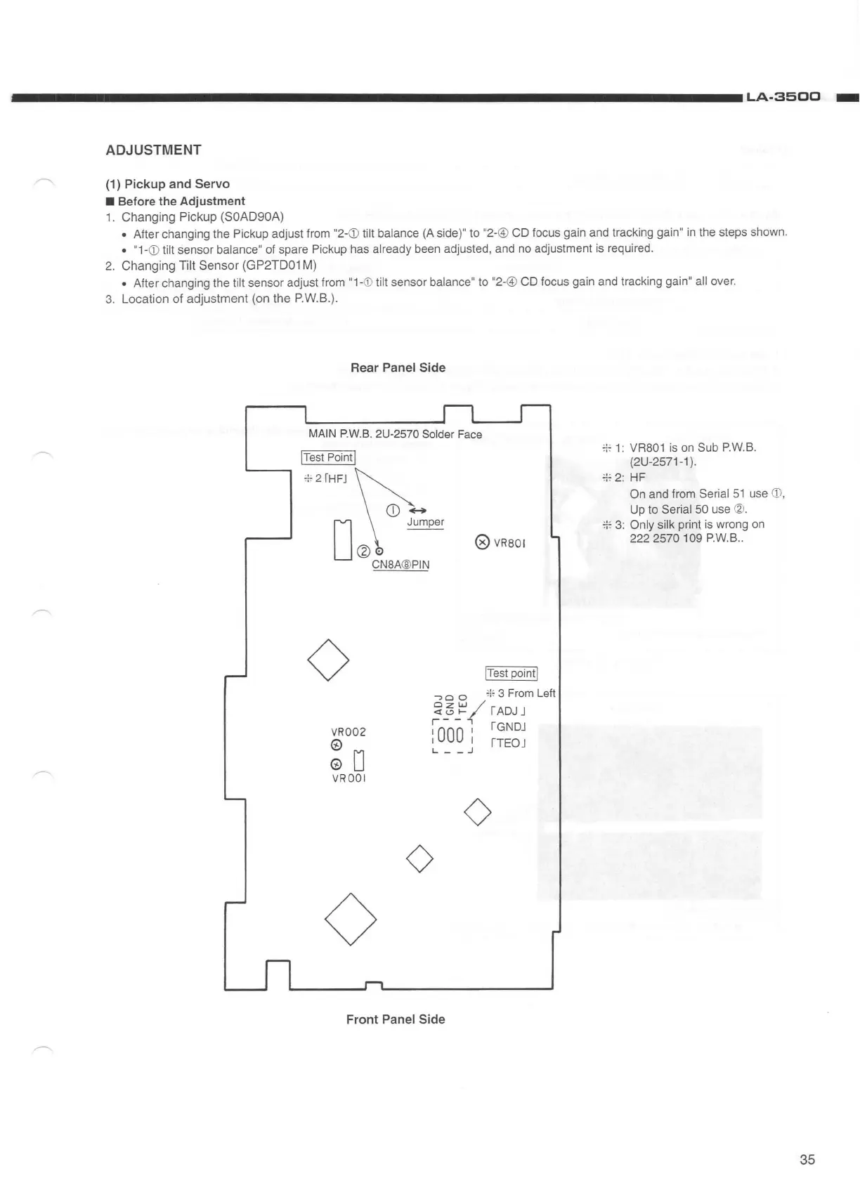
ADJUSTMENT
(1) Pickup and Servo
• Before the Adjustment
1.
Changing
Pickup (SOAD90A)
• After changing the Pickup adjust from "2-
<D
tilt balance
(A
side)" to "2-@ CD focus gain and tracking gain"
in
the steps shown.
• "1-
<D
tilt sensor balance" of spare Pickup has already been adjusted, and no adjustment is required.
2.
Changing
Tilt
Sensor
(G
P2TD0
1
M)
• After changing the tilt sensor adjust from "1-
CD
tilt sensor balance" to "2-@ CD focus gain and tracking gain" all over.
3.
Location
of
adjustment
(on
the
P.W.B.).
Rear Panel Side
MAIN
P.W.B
. 2U-2570 Solder
Fa
ce
!Test Point I
;;
; 2
fHFJ
CD
......
@
VRBOI
D
Jumper
@·
CNBA
@
PIN
0
VR002
©
© D
VROOI
0
!Test
point!
,
0
0
i
li
3 From Left
ClZW
/
~"'
1-
I
ADJ
J
r-
-
.,
I
000
I rGNDJ
I I
ITEOJ
L - - j
0
0
Front Panel Side
+
1:
VRB01
is
on
Sub P
.W.
B.
(2U-2571-1).
;;~
2:
HF
On and from Serial
51
use
<D
,
Up to Serial 50 use
<2!
.
+
3:
Only silk print is wrong
on
222 2570 109 P.W.B
..
35