-LA-3500
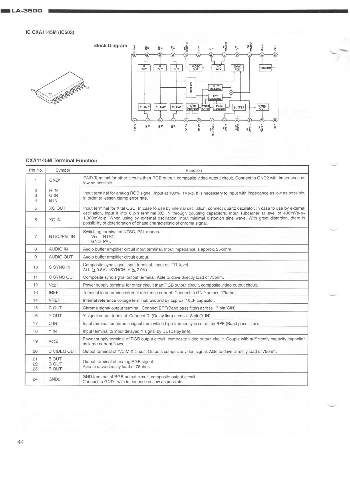
IC CXA 1145M (IC503)
Block Diagram
12
CXA
1145M Terminal Function
Pin
No.
Symbol
Function
1
GND1
GND Terminal for other circuits than RGB output, composite video output circuit. Connect to GND2 with impedance as
low as possible.
2
RIN
Input terminal for analog RGB signal. Input at 100%
=1
Vp-p.
It
is necessary to input with impedance as low as possible,
3
GIN
4
BIN
in
order to lessen clamp error rate.
5
XO
OUT Input terminal for X'tal OSC.
In
case to use by internal oscillation, connect quartz oscillator.
In
case to use by external
oscillation,
input it into 6 pin terminal
XO
IN
through coupling capacitors. Input subcarrier
at
level of 400mVp-
p-
6
XOIN
1,000mVp-p. When using by external oscillation, input minimal distortion sine wave. With great distortion, there is
possibility of deterioration of phase characteristic of chroma signal.
Switching terminal
of NTSC , PAL modes.
7
NTSC/PAL
IN
Vee
NTSC
GND PAL
8
AUDIO
IN
Audio buffer amplifier circuit input terminal.
Input
impedance
is
approx, 25kohm.
9
AUDIO OUT
Audio buffer amplifier circuit output.
10 C SYNC
IN
Composite sync signal input terminal. Input
on
TTL
le
vel.
At
L
G;.
0.8V) :SYNCH H
~
2.0V)
11
C SYNC OUT
Composite sync signal output terminal. Able to drive directly load of 75ohm.
12
Vc
c1
Power supply terminal for other circuit than RGB output circuit, composite video output circuit.
13
IREF
Terminal
to determine internal reference current. Connect to GND across 27kohm.
14 VREF
Internal reference voltage terminal. Ground by approx. 1
OftF
capacitor.
15
GOUT
Chroma signal output terminal. Connect BPF(Band pass filter) across 17 pin{CIN).
16
YOUT
Y-signal output terminal. Connect DL(Delay line) across 18 pin(Y
IN)
.
17
GIN
Input terminal for chroma signal from which high frequeucy is cut off by BPF (Band pass filter).
18
YIN
Input terminal to input delayed Y signal by DL (Delay line).
19 Vcc2
Power
supply terminal of RGB output circuit, composite video output circuit. Couple with sufficiently capacity capacitor
as large current flows.
20 C VIDEO OUT
Output terminal
of Y/C MIX circuit. Outputs composite video signal. Able
to
drive directly load of 75ohm.
21
BOUT
Output terminal of analog RGB signal.
22
GOUT
23
ROUT
Able to drive directly load of 75ohm.
24
GND2
GND
terminal of RGB output circuit, composite output circuit.
Connect to
GND1
with impedance as low as possible.
44