Chapter 2 Engineering Design of Servo Mechanism
24
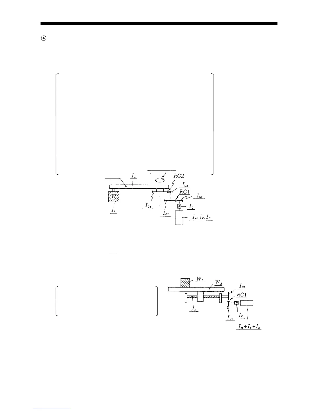
Calculation of total inertia moment (I) (conversion into the motor shaft's)
(a) Revolving arm (Fig. 2-11).
I (Nms
2
) = (I
L
+ I
A
+ I
G4
) × (RG1 × RG2)
2
··············· (Deceleration 2 step part)
+ (I
G3
+ I
G2
) × (RG1)
2
······················· (Deceleration 1 step part)
+ (I
G1
+ I
C
+ I
M
+ I
E
+ I
B
) ···················· (No deceleration part) ················ Equation (4)
Where
I
L
: Inertia moment of load W arm revolution shaft (Nms
2
)
I
A
: Inertia moment of arm revolution shaft (Nms
2
)
I
G1
: 1st step pinion inertia moment (Nms
2
)
I
G2
: 1st step gear inertia moment (Nms
2
)
I
G3
: 2nd step pinion inertia moment (Nms
2
)
I
G4
: 2nd step gear inertia moment (Nms
2
)
I
c
: Coupling inertia moment (Nms
2
)
I
M
: Motor armature inertia moment (Nms
2
)
I
E
: Encoder inertia moment (Nms
2
)
I
B
: Built-in brake inertia moment (Nms
2
)
RG1 : First step gear ratio (1/n)
RG2 : Second step gear ratio (1/n)
Fig. 2-11 Revolving arm
(b) Linear movement arm (Fig. 2-12)
IWW RG
LA
(Nms )
2
2
1
2
2
()
··············(Deceleration 2 step part)
+ (I
S
+ I
G2
) × (RG1)
2
·····································(Deceleration 1 step part)
+ I
G1
+ I
C
+ I
M
+ I
E
+ I
B
·································(No deceleration part)··················· Equation (5)
Where
W
L
: Load weight (kg)
W
A
: Arm weight (kg)
I
S
: Inertia moment of ball screw (Nms
2
)
l : Lead of ball screw (m/rev.)
Fig. 2-12 Linear movement arm
Motor
Ball screw etc.
Arm
Arm revolving shaft
Motor