()
.
····································································· Equation (6)
Where
D : Outer diameter (m)
d : Inner diameter (m)
h : Thickness (m)
: Specific gravity (kg/m
3
)
* When inertia is expressed by GD
2
,
divide it by 4 g.
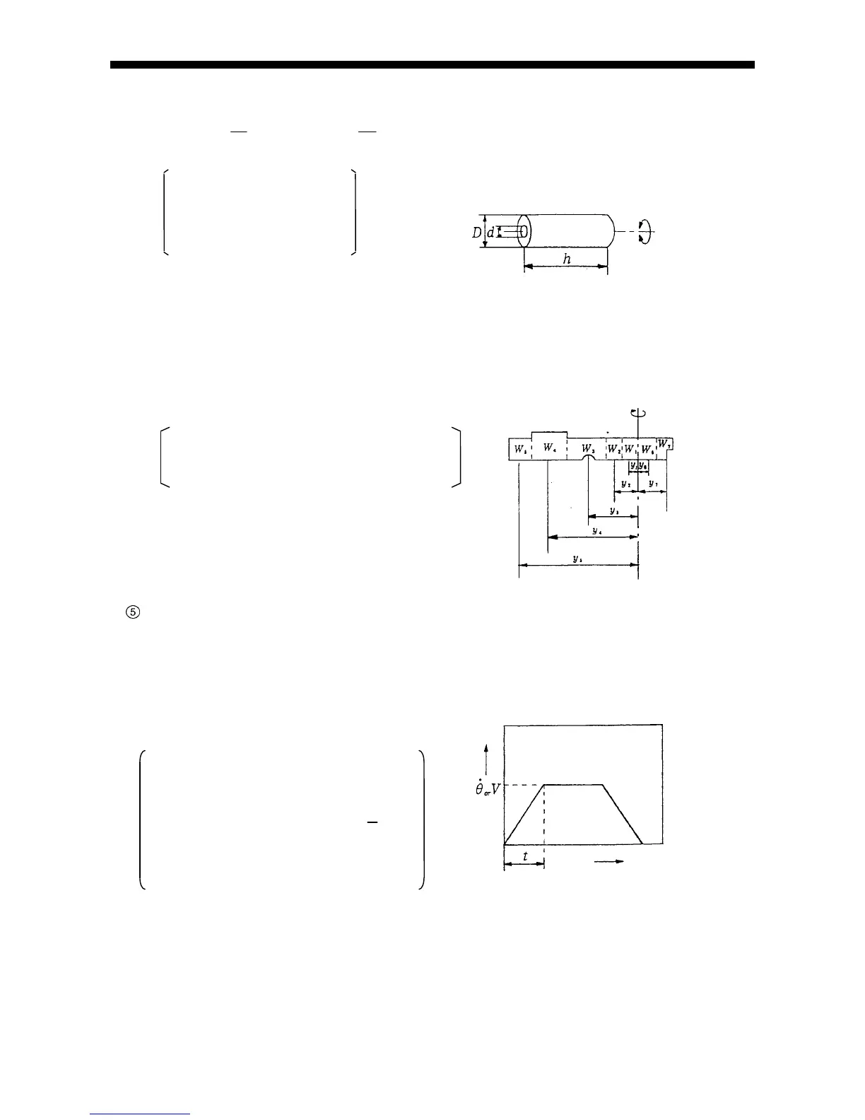
Fig. 2-13 Rotor
(d) Calculation of complex shape unit inertia moment (I
2
) (Fig. 2-14)
Inertia moment of complex shape unit can not be achieved by the equation. Therefore, divide the unit
into parts and achieve the inertia moment by each part and add such moments.
IWy
i
in
ii2
(Nms
2
1
2
)( )
························································································· Equation (7)
Where
W
i
= Divided part weight (kg)
y
i
= Distance from center of revolution
to center of divided part (m)
Fig. 2-14 Complex shape unit
Calculation of motor shaft angular acceleration (ω)
(a) Revolving arm
(rad / s
2
) =
٠2
/ 360٠t٠RG ··············································································· Equation (8)
(b) Linear movement
(rad / s
2
) = V٠2
/ l٠t٠RG
···················································································· Equation (9)
Where
t = Acceleration time (sec.)
= Arm revolving speed (
/s)
V = Linear speed (m/s)
RG = Total deceleration ratio
(
1
n
)
l =
Fig. 2-15 Angular acceleration
Ball screw,
Rack & Pinion
}
Lead (m/rev.)
Time
Speed
 Loading...
