Chapter 2 Engineering Design of Servo Mechanism
26
Friction torque of transmission system, etc. (T
FD
)
Divide the friction torque of the slide part, seal, speed reducer, etc. by deceleration ratio to make the
quotient as the friction torque in conversion into the motor shaft. Especially be sure to know that the
transmission mechanism friction torque before deceleration is directly applied to the motor.
Gravity holding torque (Tg)
When the gravity needs to be held, divide the holding unit weight by gear ratio to make the quotient as
the gravity torque in conversion into the motor shaft's. When taking gravity balance by air cylinder or
counter weight, the gravity holding torque is "0". Be sure to check, however, the slide resistance of air
cylinder and the addition of inertia moment.
Particular load torque (Ts)
When the degree of freedom is 2 or more, sometimes interference torque or centrifugal force or corioli's
force is applied by other shaft movement. Achieve the sum of these forces by mechanism construction
or motion speed and divide it by gear ratio to make the quotient as the torque in conversion into the motor
shaft's.
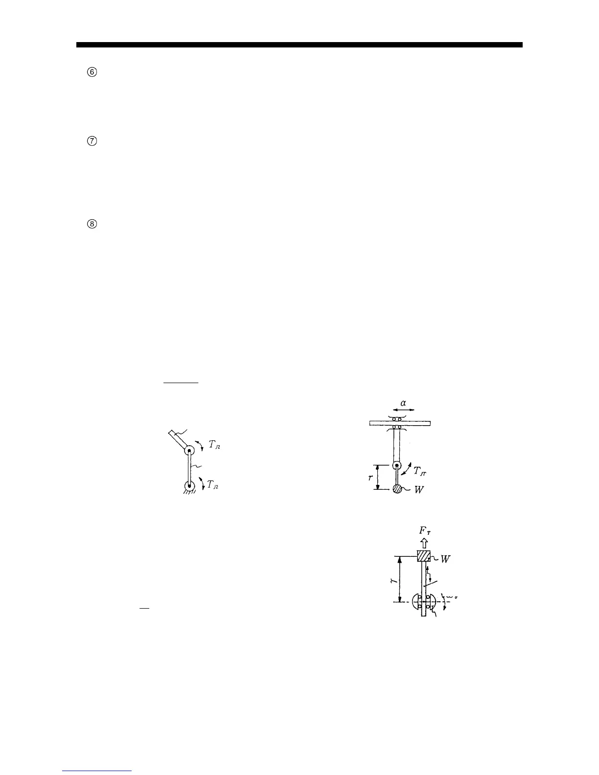
(a) Example of interference torque
(i) On two joint arm, second arm drive torque (T
J2
) is applied to first arm. (Fig. 2-16)
(ii) Also in combination of linear movement and revolving shaft movement, acceleration () of linear
shaft is applied to the offset load (W) of the revolving shaft and torque (Tr) of the revolving shaft
which is in proportion to the offset distance (r) occurs. (Fig. 2-17)
T
Wr
g
JT
(g: Gravitational acceleration 9.8 m/s
2
)
Fig. 2-16 Interference torque i Fig. 2-17 Interference torque ii
(b) Example of centrifugal force (F
T
)
On an object (W) on the revolving shaft, centrifugal force
(F
T
) occurs from center to outside in proportion to the square
of revolving shaft angular speed (
) and the revolving
radius (r) (Fig. 2-18)
F
W
g
T
2
*
On fig. 2-18, linear shaft supports centrifugal force.
Fig. 2-18 Centrifugal force
First arm
Second arm
Revolving shaft
Linear shaft