2
2.3 Lube Oil Circuit Engine Description
26 335 0
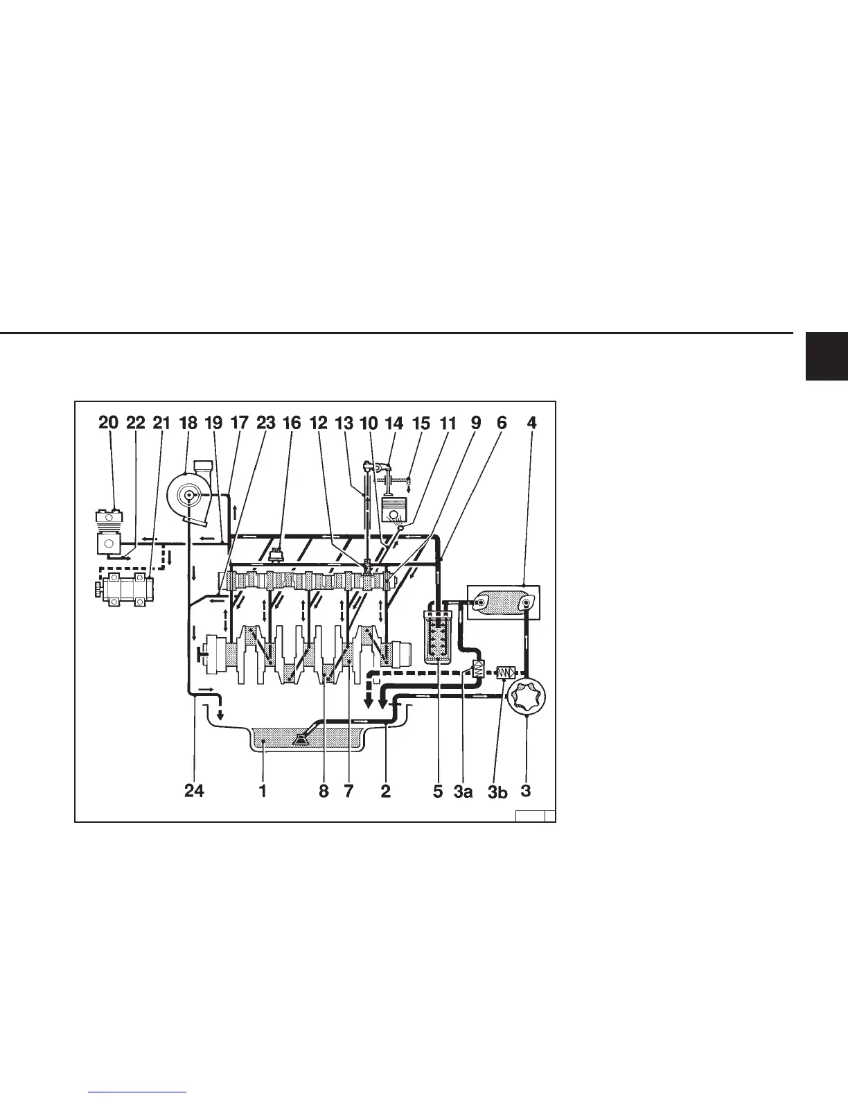
2.3.2 Lube Oil Circuit Schematic
1013 / 1013 E
1 Oil pan
2 Air intake manifold
3 Lube oil pump
3a Back leak fuel valve
3b Pressure-relief valve
4 Lube oil cooler
5 Lube oil filter
6 Main oil gallery
7 Crankshaft bearing
8 Conrod bearing
9 Camshaft bearing
10 Spray nozzle line
11 Spray nozzle for piston cooling
12 Tappet w/ control bore for pulse lubrication
of rocker arms
13 Pushrod (designed for lube oil supply of
rocker arms)
14 Rocker arm
15 Return line to oil pan
16 Oil sensor
17 Oil line to exhaust turbocharger
18 Exhaust turbocharger
19 Oil line to compressor or hydraulic pump
20 Compressor
21 Hydraulic pump
22 Return line to compressor or hydraulic pump
23 Return to oil pan
24 Exhaust turbocharger return to crankcase