SIRIUS®
4.2 Connectors at the rear side
4.2.1 Single Slice Version USB
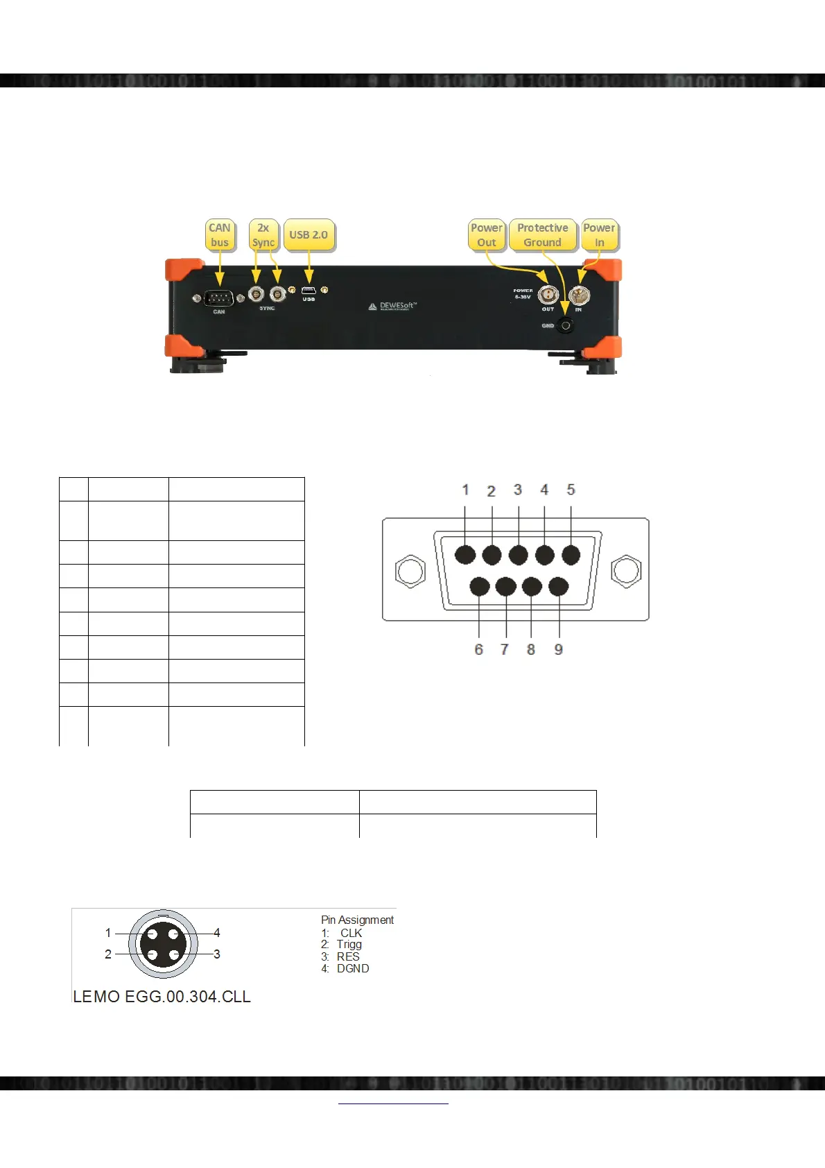
The SIRIUS® USB chassis has following connectors at the rear side.
Illustration 47: SIRIUS chassis: connectors on the back side
4.2.1.1 CAN (DSUB-9)
See also connector CAN in Illustration 47 on page 26.
Pin Name Description
Illustration 48: SIRIUS-CAN: pin-out (DSUB-9)
1 +5V 5V supply
max. current: 500mA
2 CAN_LOW CAN low
3 DGND Digital Ground
4 RES Reserved
5 RES Reserved
6 DGND Digital Ground
7 CAN_HIGH CAN high
8 RES Reserved
9 +12V 12V supply
max. current: 200mA
CAN: Specifications
Interface type CAN 2.0B, up to 1MBit/s
Special applications OBDII, J1939, CAN output
Table 5: SIRIUS-CAN specifications
4.2.1.2 Sync connectors: Pin-out (LEMO 4pin)
Illustration 49: SIRIUS Sync connector: pin-out (LEMO
4pin)
Mating connector: FGG.00.302.CLAD27Z
When IRIG-synchronisation is used, the IRIG signal is
on pins 1, 2.
Page 26/166 www.dewesoft.com Doc-Version: 1.4.2