Enclosure Overview
4.6.2.3 Option: GPS connector
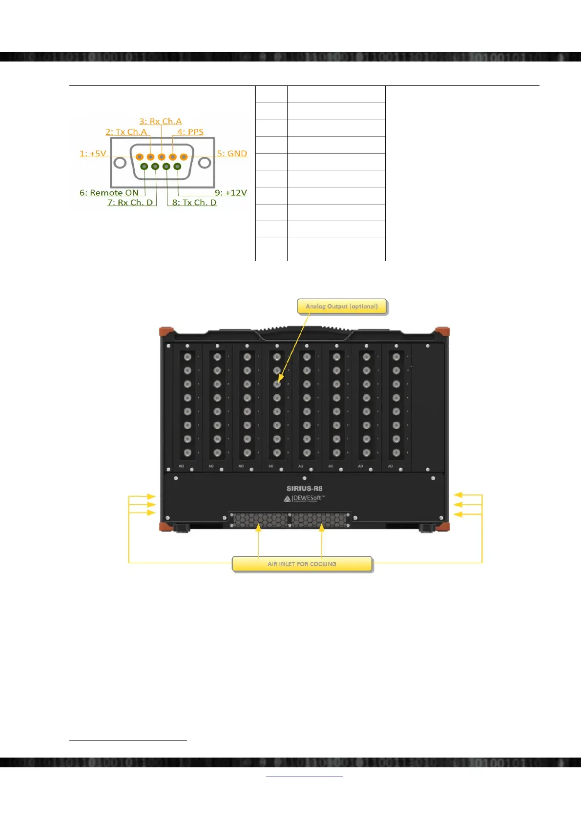
Illustration 73: GPS Connector
Pin Name
To power the system on, press the
Power switch OR apply a voltage
between 3 and 30V to Remote-On pin
To power off the system press the
Power switch or reduce the voltage
on Remote-On below 0.5V for more
than one second.
GPS port A is used for GPS-Display
or for the RF-modem when RTK
option is in use.
GPS port D is reserved. Do not
connect!
1 +5V (max. 0.5A)
2 TXD GPS port A
3 RXD GPS port A
4 GPS PPS
5 GND
6 Remote-On
6
7 RXD GPS port D
8 TXD GPS port D
9 +12V (max. 0.5A)
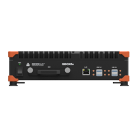
4.6.3 Rear Side
Illustration 74: SIRIUS-R8: Rearside
6 Remote-On may not be available for units before Q1/2013
Doc-Version: 1.4.2 www.dewesoft.com Page 39/166