Measurement
6 Measurement
This chapter covers topics that you should be aware of when doing your measurement with Sirius®.
6.1 Filtering
This chapter covers the filtering capabilities of the Sirius® measurement modules and of the DEWESoft® measurement
software.
6.1.1 Filtering Glossary
This chapter describes some important terms related to filtering.
6.1.1.1 Frequency response
The frequency response of a filter can be classified into a number of different bandforms describing which frequency
bands the filter passes (the passband) and which it rejects (the stopband). To discuss the Sirius® filtering, we only need
to consider 2 types frequency response:
Low pass filter
Low frequencies can pass, high frequencies are attenuated.
High pass filter
High frequencies can pass, low frequencies are attenuated.
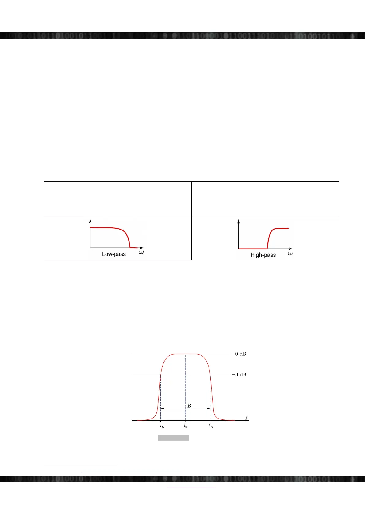
6.1.1.2 Bandwidth
Bandwidth is the difference between the upper and lower frequencies in a continuous set of frequencies. It is typically
measured in hertz, and refers to the baseband bandwidth in the context of this chapter: In the case of a low-pass filter or
baseband signal, the bandwidth is equal to its upper cut-off frequency.
The practically useful definition that we use, is that the Bandwidth will refer to the frequencies beyond which frequency
response is small (3 dB).
The diagram in Illustration 178 shows the definition of bandwidth (B) for a bandpass filter. f
0
is the centre frequency, f
H
is the higher cut-off frequency, and f
L
is the lower cut-off frequency. The 0 dB level is the level of the peak of the
bandpass response, which is not necessarily located at the centre frequency. Also the centre frequency is located at
either the arithmetic or geometric mean of the upper and lower cut-offs depending on context and conventions.
Illustration 178: Bandwidth
22
22 Image Source. https://en.wikipedia.org/wiki/File:Bandwidth_2.svg
Doc-Version: 1.4.2 www.dewesoft.com Page 127/166