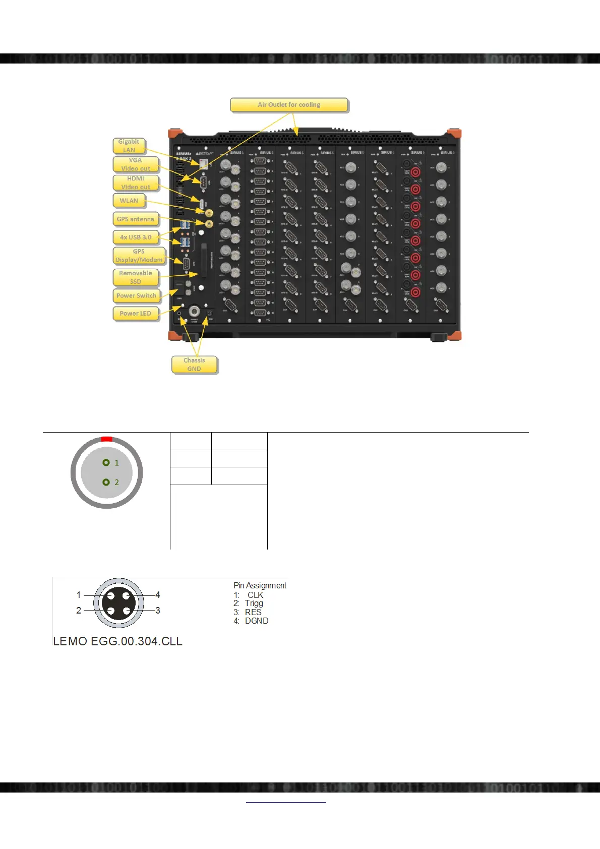
EasyManuals Logo

DEWESOFT SIRIUS User Manual

DEWESOFT SIRIUS
172 pages
To Next Page IconTo Next Page
To Previous Page IconTo Previous Page
Page #44 background imageLoading...
Page #44 background image
SIRIUS®
4.6.2 Front Side
Illustration 70: SIRIUS-R8: Frontside
4.6.2.1 Power connector
Illustration 71:
Power Connector 2pin
Pin Name L2B2f
Power connector (on the S-BOX): ECG.2B.302
Mating connector (for the cable): FGJ.2B.302
1 V+
2 GND
4.6.2.2 Sync connectors: Pin-out (LEMO 4pin)
Illustration 72: SIRIUS Sync connector: pin-out (LEMO
4pin)
Mating connector: FGG.00.302.CLAD27Z
When IRIG-synchronisation is used, the IRIG signal is
on pins 1, 2.
Since there are 2 connectors it's easy to chain several SIRIUS® chassis (or DEWE-43, DS-CAN2, etc.) together.
Note that there is no distinction between IN and OUT – it does not matter which connector you use.
Page 38/166 www.dewesoft.com Doc-Version: 1.4.2
DEWESoft® DEWESoft® DEWESoft® DEWESoft® DEWESoft® DEWESoft® DEWESoft® DEWESoft® DEWESoft® DEWESoft® DEWESoft® DEWESoft®
measurement innovation measurement innovation measurement innovation measurement innovation measurement innovation measurement innovation measurement innovation

Table of Contents

Questions and Answers:

Question and Answer IconNeed help?

Do you have a question about the DEWESOFT SIRIUS and is the answer not in the manual?

DEWESOFT SIRIUS Specifications

General IconGeneral
Resolution24-bit
IsolationChannel-to-channel and channel-to-ground
InterfaceUSB
SoftwareDewesoftX data acquisition software
BandwidthDC to 50 kHz (depending on module type)
Humiditynon-condensing
Analog InputsVoltage, IEPE, Charge, Current, Strain Gage, Thermocouple, RTD, Resistance, LVDT, Bridge

Related product manuals