EasyManuals Logo

DEWESOFT SIRIUS User Manual

DEWESOFT SIRIUS
172 pages
To Next Page IconTo Next Page
To Previous Page IconTo Previous Page
Page #84 background imageLoading...
Page #84 background image
SIRIUS®
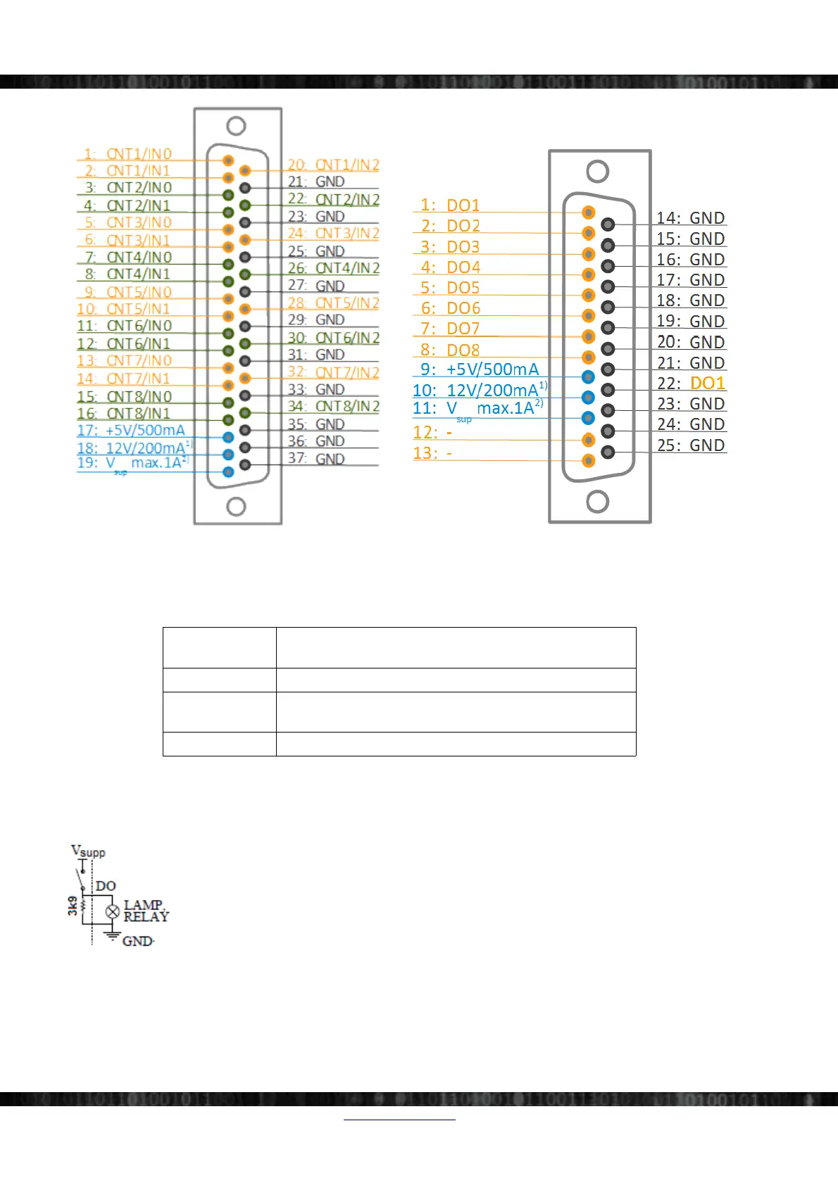
Illustration 123: DSUB 37 pins Illustration 124: DSUB 25 pins
1) this voltage is guaranteed to be <= 12V
When the supply voltage is <12V, then this voltage will be 2V lower than the supply voltage:
e.g. when the supply voltage is 10V, the voltage will be 8V
2) The supply voltage from the slice is routed to this pin.
Counters
Parallel use
8 counter/24 digital inputs
fully synchronised with analogue
Modes counting, waveform timing, encoder, tacho, gear-tooth sensor
Digital Out High side switch to supply voltage with internal 3.9 kΩ pull
down, max. 150mA, short circuit protected.
Connector type DSUB 37 male, DSUB 25 female
Table 19: STGM-DB Counter Specifications (per module)
Digital Output Configuration
Page 78/166 www.dewesoft.com Doc-Version: 1.4.2
DEWESoft® DEWESoft® DEWESoft® DEWESoft® DEWESoft® DEWESoft® DEWESoft® DEWESoft® DEWESoft® DEWESoft® DEWESoft® DEWESoft®
measurement innovation measurement innovation measurement innovation measurement innovation measurement innovation measurement innovation measurement innovation

Table of Contents

Questions and Answers:

Question and Answer IconNeed help?

Do you have a question about the DEWESOFT SIRIUS and is the answer not in the manual?

DEWESOFT SIRIUS Specifications

General IconGeneral
Resolution24-bit
IsolationChannel-to-channel and channel-to-ground
InterfaceUSB
SoftwareDewesoftX data acquisition software
BandwidthDC to 50 kHz (depending on module type)
Humiditynon-condensing
Analog InputsVoltage, IEPE, Charge, Current, Strain Gage, Thermocouple, RTD, Resistance, LVDT, Bridge

Related product manuals