OPERATOR’S MANUAL
PM200, 200E and 250 Planter Monitors
11001-1444-200702
INSTALLATION / 11
INSTALLING CONSOLE HARNESSES
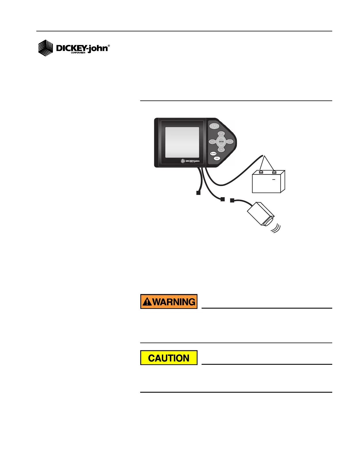
Several harnesses are located at the bottom of the monitor. These include
power, ground speed sensor, and sensor inputs (rows, lift switch, two
hopper levels, and one frequency function [shaft]).
Figure 6
Console Harnesses
1. Route the power harness to a +12 V source near the battery if
possible.
2. Route the ground speed sensor harness connection to the radar, Hall
Effect, or GPS ground speed sensor.
3. Route the implement harness to the location of choice, typically near
the drawbar.
The harnesses must not obstruct movement of the operator or of
the moving parts of the tractor or implement. Take care when
routing harnesses to secure them at proper locations; provide
slack as needed to allow for movement.
Poor +12 V connections may cause intermittent console operation.
Be sure to connect the power harness to a clean, well-conditioned
source (direct battery connection is preferred).
+
Ground
Speed
Battery
Implement
(rows and accessories)