OPERATOR’S MANUAL
PM200, 200E and 250 Planter Monitors
11001-1444-200702
MENU SETUP SCREEN (OPTIONAL) / 34
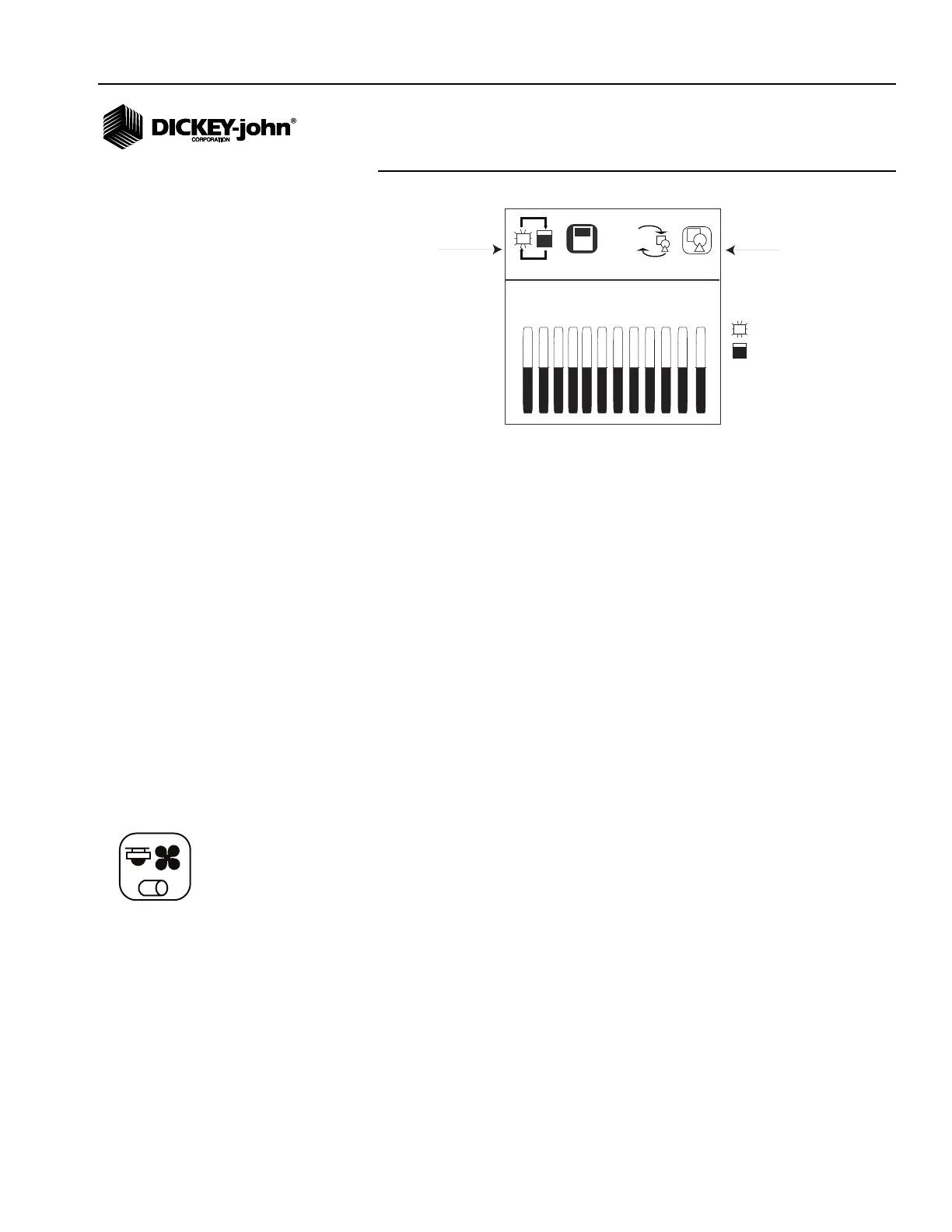
Figure 24
Display Setup Screen
To Change the Row Indicator Type:
1. From the Menu screen, select the Display Screen Setup icon and
press Enter to display the screen.
2. At the Row Indicator Status icon, press Enter.
3. Use the Arrow keys to toggle between the bar graph or or blinking box
symbol.
4. Press Enter to accept.
To Change the Graphic/Text Settings:
1. From the Menu screen, select the Display Screen Setup icon and
press Enter to display the screen.
2. Use the Right Arrow key to highlight the Graphic/Text icon and press
Enter.
3. Use the Arrow keys to toggle between the graphic and text selection.
4. Press Enter to accept.
ACCESSORY SETUP (SHAFT SENSOR) (PM250)
To add a shaft sensor and its performance characteristics (calibration
values, limits, etc.) to the monitoring inputs, it must be activated by entering
a calibration constant. If minimum or maximum alarms are desired, the
limits can be added to the calibrated sensors.
blinking box
bar graph
SET LOWER TYPE
Row Indicator
Type
aA
1 2 3 4 5 6 7 8 9 10 11 12
Text/Graphics
Accessory icon