AT commands I/O settings commands
XBee®-PRO 900HP/XSC RF Modules
102
PR (Pull-up/Down Resistor Enable)
The bit field that configures the internal pull-up/down resistor status for the I/O lines. If you set a PR
bit to 1, it enables the pull-up/down resistor; 0 specifies no internal pull-up/down resistor. The
following table defines the bit-field map for PR command.
PR and PD only affect lines that are configured as digital inputs or disabled.
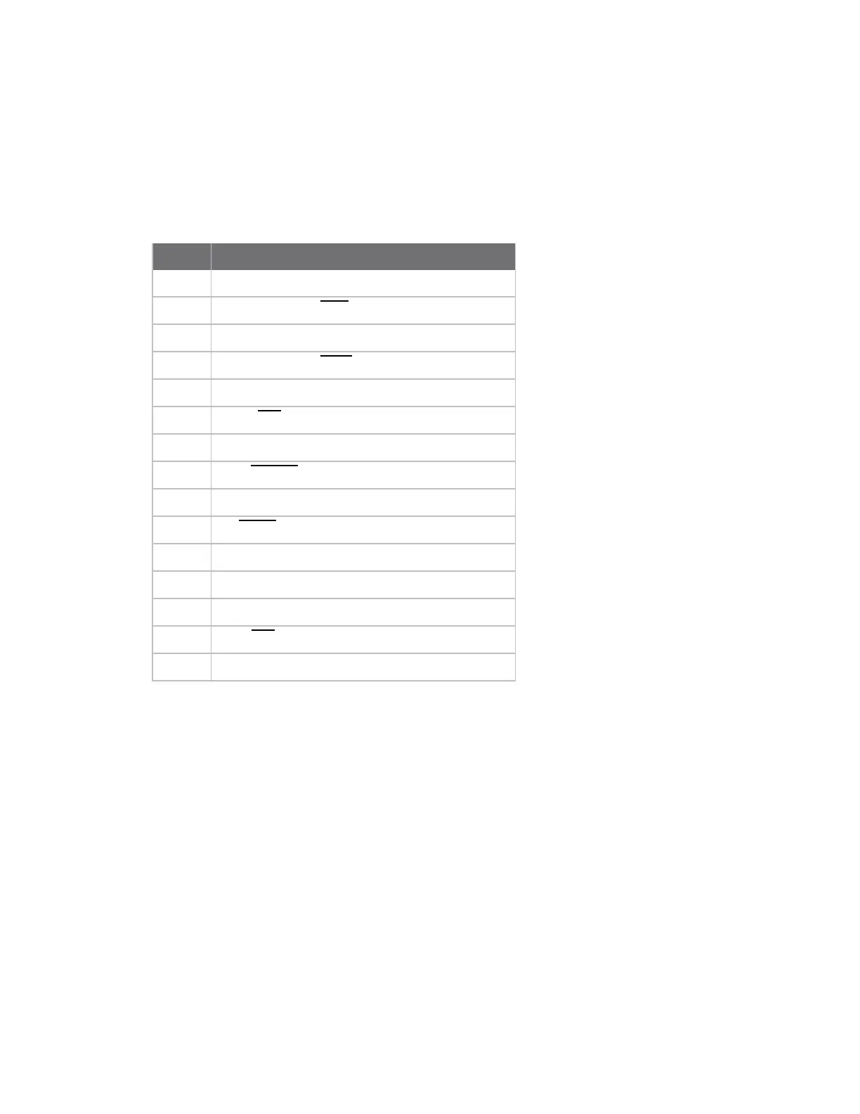
The following table defines the bit-field map for PR and PD commands.
Bit I/O line
0 DIO4 / AD4 / SPI_MOSI
1
DIO3 / AD3 / SPI_SSEL
2 DIO2 / AD2 / SPI_SCLK
3
DIO1 / AD1 / SPI_ATTN
4 DIO0 / AD0
5
DIO6 / RTS
6 SLEEP_REQUEST
7
DIN / CONFIG
8 DIO5 / AD5 / ASSOCIATE
9
On/SLEEP
10 DIO12 / SPI_MISO
11 DIO10 / PWM0 / RSSI
12 DIO11/ PWM1
13
DIO7/CTS
14 PWM0 / DOUT
Parameter range
0 - 0x7FFF (bit field)
Default
0x7FFF
M0 (PWM0 Duty Cycle)
The duty cycle of the PWM0 line (pin 6).
Use the P0 command to configure the line as a PWM output.
Parameter range
0 - 0x3FF
Default
0
 Loading...


