XSC firmware Electrical characteristics
XBee®-PRO 900HP/XSC RF Modules
183
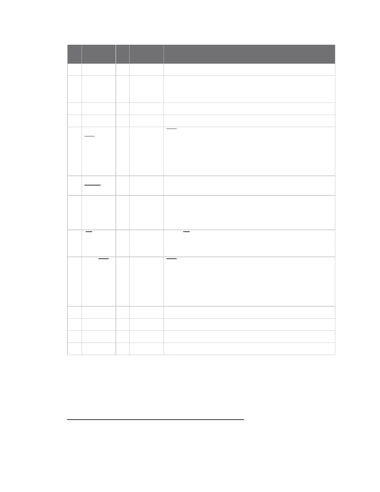
Pin
Public
signal I/O
When
active Function
8 NC Do not connect
9 DI3 /
SLEEP
1
I High By default, DI3 pin is not used. To configure this pin to support
sleep modes, see Sleep mode, SM (Sleep Mode) and PW (Pin
Wakeup).
10 GND Ground
11 O Drivenhigh Do not connect
12 DO2/
CTS/RS-
485Enable
O Low CTS (clear-to-send) flow control. When pin is driven low, UART
host is permitted to send serial data to the module. Refer
toUART-interfaced data flow and for more information.
RS-485 Enable. To configure this pin to enable RS-485 (2-wire
or 4-wire) communications, refer to UART-interfaced data flow
and .
13 ON /
SLEEP
O High High = Indicates power is on and module is not in Sleep mode.
Low = Sleep mode or module is unpowered.
14 VREF I
N/A
Not used on this module. For compatibility with other XBee
devices, we recommend connecting this pin to a voltage
reference if analog sampling is desired. Otherwise, connect to
GND.
15 TX / PWR O
N/A
Low = TX - Pin pulses low during transmission
High = PWR - Indicates power is on and module is not in Sleep
mode.
16 DI2 / RTS /
CMD
2
I Low RTS (request-to-send) flow control - By default, this pin is not
used. To configure this pin to regulate the flow of serial data
exiting the module, refer to UART-interfaced data flow and RT
(DI2 Configuration).
CMD. Refer to Configuration and commands and RT (DI2
Configuration) to enable binary command programming.
17 O Driven low Do not connect
18 O Driven low Do not connect
19 O Driven low Do not connect
20 O Driven low Do not connect
Electrical characteristics
When the transmitting device receives the first byte of data in the DIN buffer, it initiates the data flow
sequence. As long as the TX device is not already receiving RF data, it converts the data in the DIN
buffer into packets and transmits them over-the-air to the receiving device.
1
Has a pull up resistor. S3B has internal pull-up.
2
Has a pull down resistor. S3B has internal pull-up.