Configuration and commands Diagnostic commands
XBee®-PRO 900HP/XSC RF Modules
221
RP (RSSI PWM Timer)
Enables a pulse-width modulated (PWM) output on the CONFIG pin. We calibrate the pin to show the
difference between received signal strength and the sensitivity level of the device. PWM pulses vary
from zero to 95 percent. Zero percent means the RF signal the device receives is at or below the
device's sensitivity level.
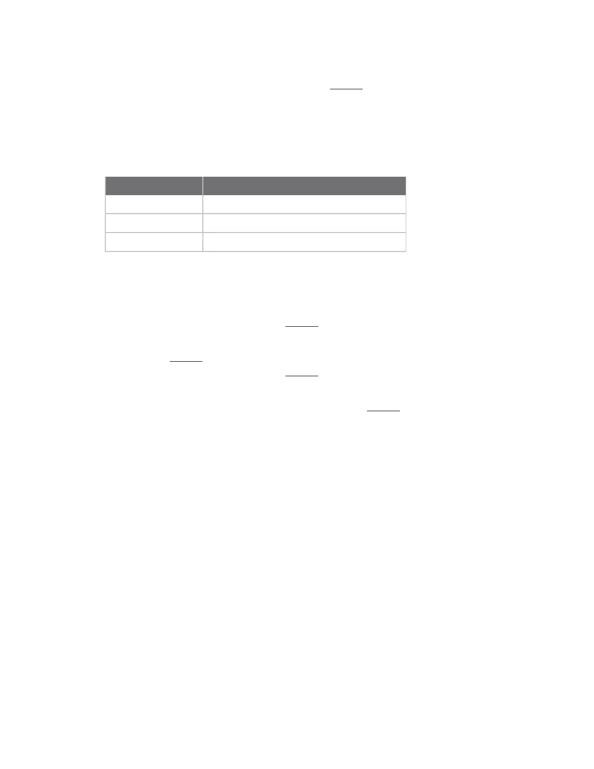
The following table shows dB levels above sensitivity and PWM values. The total time period of the
PWM output is 8.32 ms. PWM output consists of 40 steps, so the minimum step size is 0.208 ms.
dB above sensitivity PWM percentage (high period / total period)
10 47.5%
20 62.5%
30 77.5%
A non-zero value defines the time that PWM output is active with the RSSI value of the last RF packet
the device receives. After the set time when the device has not received RF packets, it sets the PWM
output low (0 percent PWM) until the device receives another RF packet. It also sets PWM output low
at power-up. A parameter value of 0xFF permanently enables PWM output and always reflects the
value of the last received RF packet.
The PWM output and Config input share the CONFIG /RSSI pin. When the device is powered, the Config
pin is an input. During the power-up sequence, if RP is a non-zero value, the firmware configures the
Config pin as an output and sets it low until the device receives the first RF packet. With a non-zero RP
parameter, the CONFIG pin is an input for RP ms after power up.
The PWM output and Config input share the CONFIG pin. When the device is powered, the Config pin is
an input. During the power-up sequence, the device reads Config pin to determine whether to go to AT
command mode. The Config pin is then configured as an output and set to low until the device
receives the first RF packet. With a non-zero RP parameter, the CONFIG pin is an input for RP ms after
power up.
Binary command
0x22 (34 decimal)
Parameter range
0 - 0xFF [x 100 ms]
Default
0 (disabled)
Bytes returned
1
RZ (DI Buffer Size)
Reads the size of the DI buffer of the UART receiving device.
Multiply the DI buffer size by 1.5 to determine the DO buffer size.
Binary command
0x2C (44 decimal)