XBee-PRO XSC RF Module operation Flow control
XBee®-PRO 900HP/XSC RF Modules
193
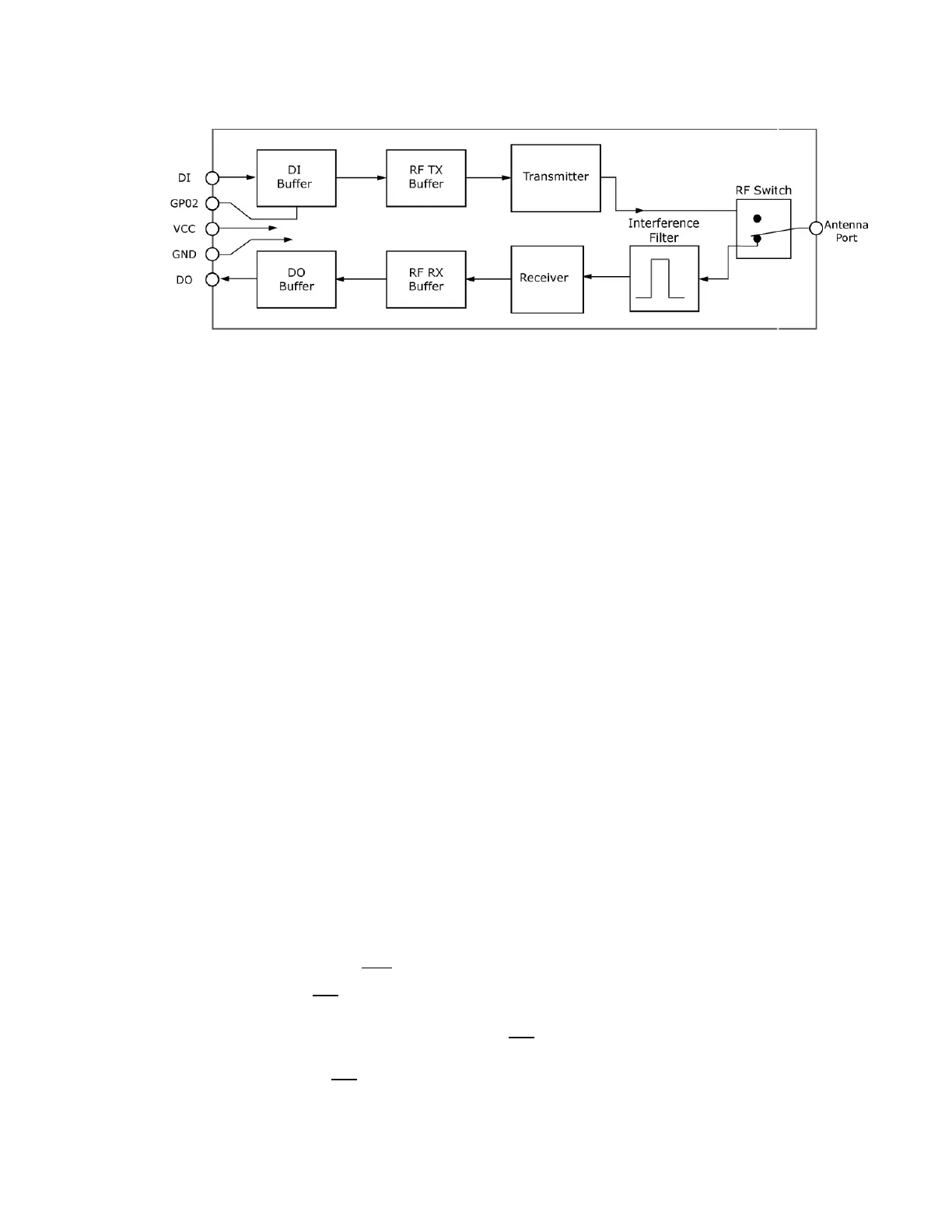
Data In (DIN) buffer and flow control
When serial data enters the device through the DIN pin (pin ), it stores the data in the DIN buffer until
it can process the data.
When the firmware satisfies the RB and RO parameter thresholds, the device attempts to initialize an
RF transmission. If the device is already receiving RF data, it stores the serial data in the device's DIN
buffer.
1. The device does not receive any serial characters for the amount of time set with in the RO
command; see RO (Packetization Timeout).
2. The device receives the maximum number of characters that fits in an RF packet.
3. The device receives the Command Mode sequence.
If the DIN buffer becomes full, you must implement hardware or software flow control in order to
prevent overflow (loss of data between the host and the device). To eliminate the need for flow
control:
1. Send messages that are smaller than the DIN buffer size. The size of the DIN buffer varies
according to the packet size (PK parameter) and the parity setting (NB parameter) you use.
2. Interface at a lower baud rate (BD parameter) than the RF data rate of the firmware (BR
parameter) of the firmware.
In the following situations, the DIN buffer may become full and overflow:
1. If you set the serial interface data rate higher than the RF data rate of the device, the device
receives data from the host faster than it can transmit the data over-the-air.
2. If the device receives a continuous stream of RF data or if the device monitors data on a
network, it places any serial data that arrives on the DIN pin (pin ) in the DIN buffer. It
transmits the data in the DIN buffer over-the-air when the device no longer detects RF data in
the network.
Hardware flow control (CTS)
The firmware asserts CTS before the DIN buffer is full so it has time to send the signal and the host
has time to stop sending data.
When the DIN buffer is full, the firmware de-asserts CTS (high) to signal the host to stop sending data;
refer to FT (Flow Control Threshold) and CS (DO2 Configuration).
The firmware re-asserts CTS after the DIN buffer has 34 bytes of memory available.
 Loading...


