SECTION 1 – ACTUATOR INSTALLATION
Prior to beginning the installation of the swing gate actuator, we suggest that you become familiar
with the instructions, illustrations, and wiring guide-lines in this manual. This will help insure that your
installation is performed in an efficient and professional manner.
The proper installation of the vehicular swing gate actuator is an extremely important and integral part
of the overall access control system. Check all local building ordinances and building codes prior to
installing this operator. Be sure your installation is in compliance with local codes.
1.1 Technical Specifications
Class of Operation: Class I Residential Swing Gate Actuator
Type of Gate: Vehicular Swing Gates Only
Motor RPM: 1400
Max Thrust: 300daN
Voltage / Phase: 115 VAC Single Phase Input Power
24 VDC Operating Power
Current: 3 amps
Max Gate Length: 14 Ft.
Useful Rod Stroke 14 inches
Cycles / Hr: 10/Hr
Speed: 90° in approximately 20 seconds
Entrapment Protection: Primary - Inherent adjustable current sensor (Type A)
Secondary - Provision for connection of non-contact (Type
B1) sensors.
1
2
3
4
3
4
5
6
7
8
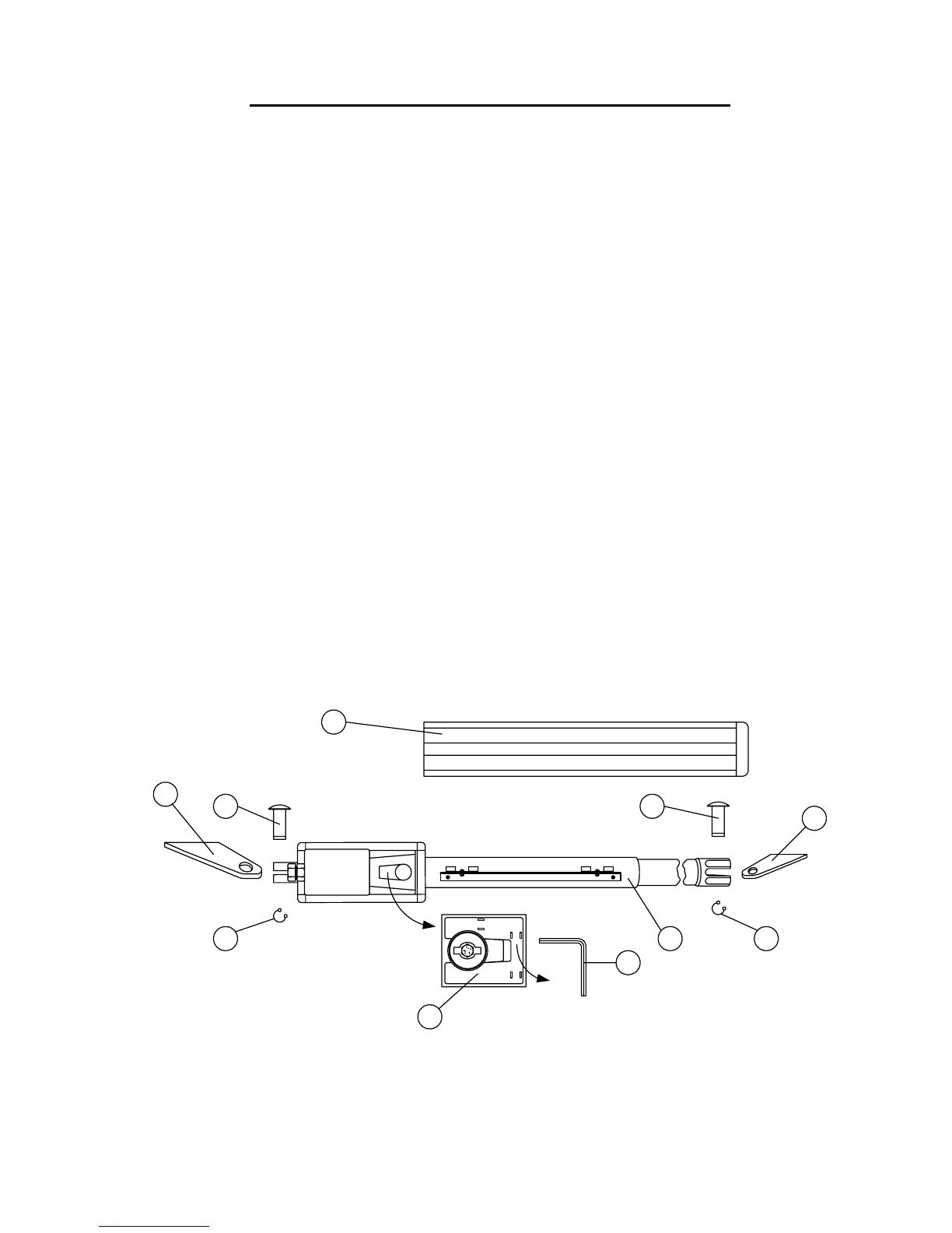
1. Actuator Cover 5. Front Mounting Bracket
2. Rear Mounting Bracket 6. Manual Release Cover
3. Clevis Pin 7. Manual Release Allen
4. Retaining Pin 8. Actuator
Figure 1
Page 11