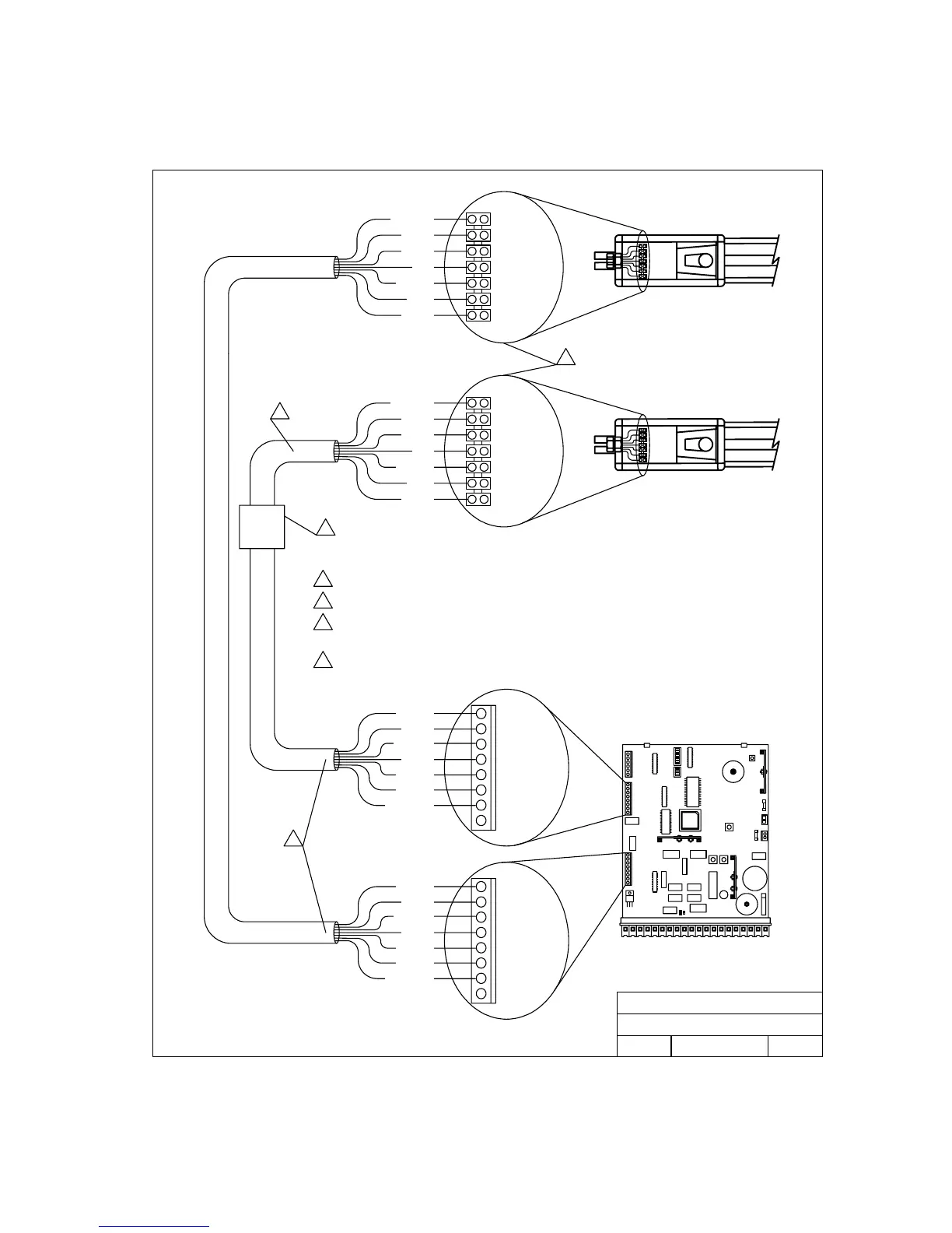
2.3 Actuator Wiring
Connect each actuator cable to the control panel as shown below. Be sure that wiring and
connections are made in accordance with local electrical codes.
DOORKING, INC., INGLEWOOD, CA 90301
Title:
Date: Rev.Dwg. No.
Actuator Wiring
C
12/03 M6001-065-3
1. Motor
2. Motor
3. Limit
4. Slow Dwn
5. Limit
6. Slow Dwn
7. Common
8. Common
1. Motor
2. Motor
3. Limit
4. Slow Dwn
5. Limit
6. Slow Dwn
7. Common
8. Common
Common
Slow Dwn
Limit
Slow Dwn
Limit
Motor
Motor
Common
Slow Dwn
Limit
Slow Dwn
Limit
Motor
Motor
MASTER
SLAVE SLAVE
SLAVE
1
2
MASTERSLAVE
3
MASTER
MASTER MASTER
Brown
Grn/Wht
Blue
Orange
Red
Yellow
Green
Brown
Grn/Wht
Blue
Orange
Red
Yellow
Green
Brown (1)
Grn/Wht (Yel)
Green (6)
Yellow (5)
Red (4)
Orange (3)
Blue (2)
Brown (1)
Grn/Wht (Yel)
Green (6)
Yellow (5)
Red (4)
Orange (3)
Blue (2)
1
Junction box for slave actuator (not supplied).
2
Slave interface cable (not supplied).
3
Actuators are pre-wired. Terminals shown for reference.
4
Earlier versions of the actuators had numbered wires rather than colored wires. The number to the right of
the wire color indicates the older wiring scheme and is shown here for reference only. There was also a
white wire (not shown) in the earlier units that was not used and not connected.
4
Figure 14
Page 19