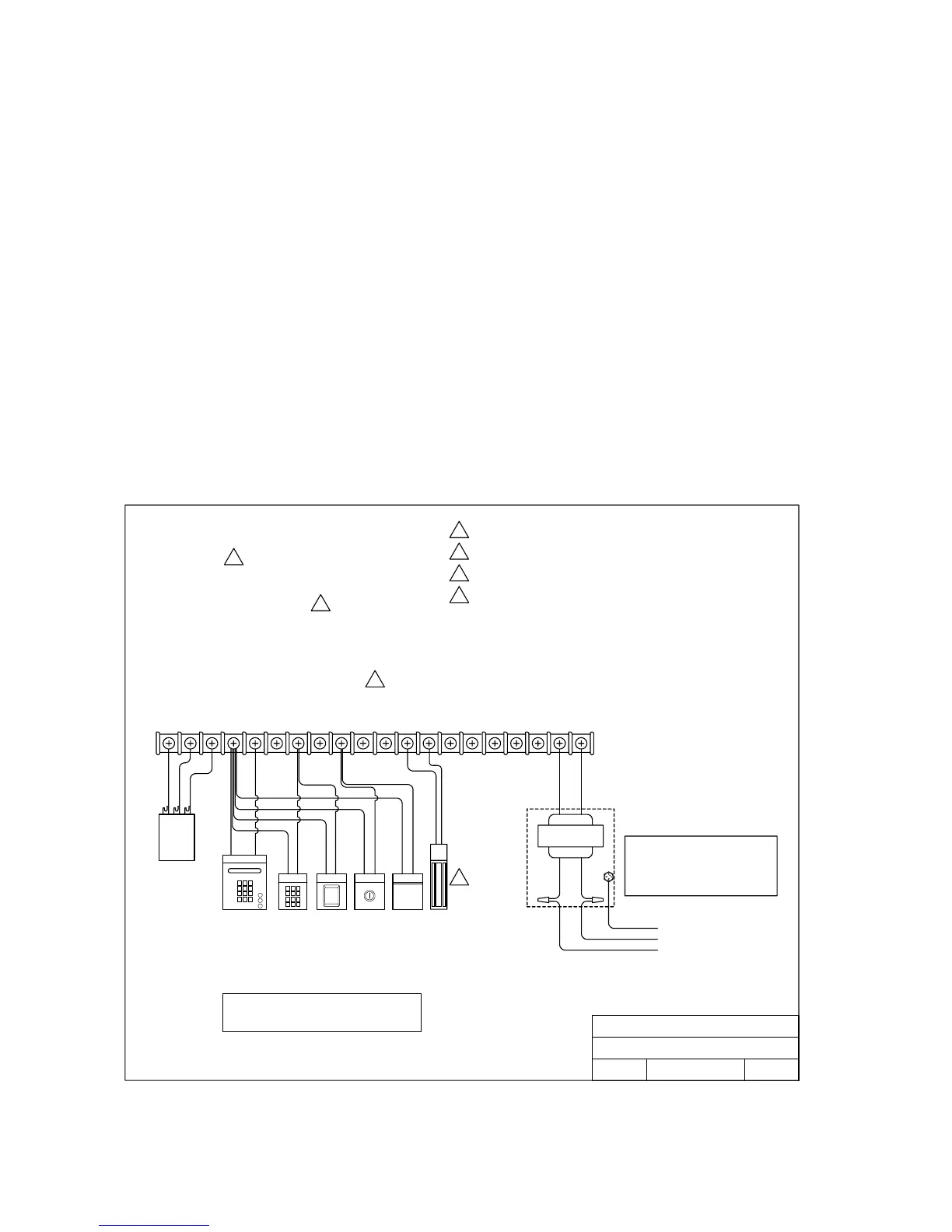
2.4 Main Terminal Control Wiring
Controls must be far enough from the gate so that the user is prevented from coming in
contact with the gate while operating the controls. Outdoor or easily accessible controls
should have a security feature to prevent unauthorized use.
• Connect optional control devices to the main terminal strip as shown (fig. 16). Be sure that all
electrical connections are made in accordance with local electrical codes. Use 18 AWG wire
for all low voltage wiring, maximum distance 3000 feet. Use a low voltage surge suppresser,
DoorKing P/N 1878-010 if low voltage wire runs exceed 1000 feet. All inputs to the terminal
strip must be NORMALLY OPEN.
• Reversing input (Terminal 8) only functions while the gate is in the closing cycle and should
not be used as an input for a secondary entrapment protection device for the open gate
cycle. See section 2.2.2 for secondary entrapment protection device wiring.
• Do not power any devices from the circuit board other than a low voltage radio receiver.
• If magnetic lock is used, be sure it is set for 24 Volt operation.
1
2
3
3-Wire
Receiver
Radio Pwr
Relay
24V Com
1 2 3 4 5 6 7 8 9 1011121314151617181920
24V COMMON
24V COMMON
24V COMMON
24V COMMON
RADIO RELAY / OPEN INPUT
24V RADIO PWR
OPEN INPUT / EXIT LOOP LOGIC OUTPUT
NOT USED
REVERSE / SHADOW INPUT
RELAY
RELAY
24 VDC MAGLOCK OUTPUT
24 VDC MAGLOCK OUTPUT
NOT USED
NOT USED
NOT USED
24V COMMON
24 VAC INPUT
24 VAC INPUT
ALARM RESET
Fire
Dept
Telephone
Entry
Digital
Keypad
Card
Reader
Key
Switch
Emergency
Access
DKGL-S12-1(L)
4
Note:
1. All inputs are N.O. (Normally Open)
2. Terminals 1, 5, 7, 9 and 18 are Common
Function dependant on SW1, switch 3
Function dependant on SW1, switch 5
Function dependant on SW2, switch 1, 2
1
2
3
4
Maglock must be set for 24 V operation
Rev.Dwg. No.
DOORKING, INC., INGLEWOOD, CA 90301
Title:
Date:
Main Terminal Control Wiring
B
5/04 M6001-065-4
115 VAC
Input Power
Transformer enclosure located in
control box. Wire nut 115 VAC
input power to Black and White
transformer wires.
WHITE
BLACK
RED
RED
BLACK
WHITE
GREEN
Figure 15
Page 20