2.8 Loop Detector and Loop Wiring
• Loops and loop detectors are required to provide protection to vehicular traffic through the
gate system.
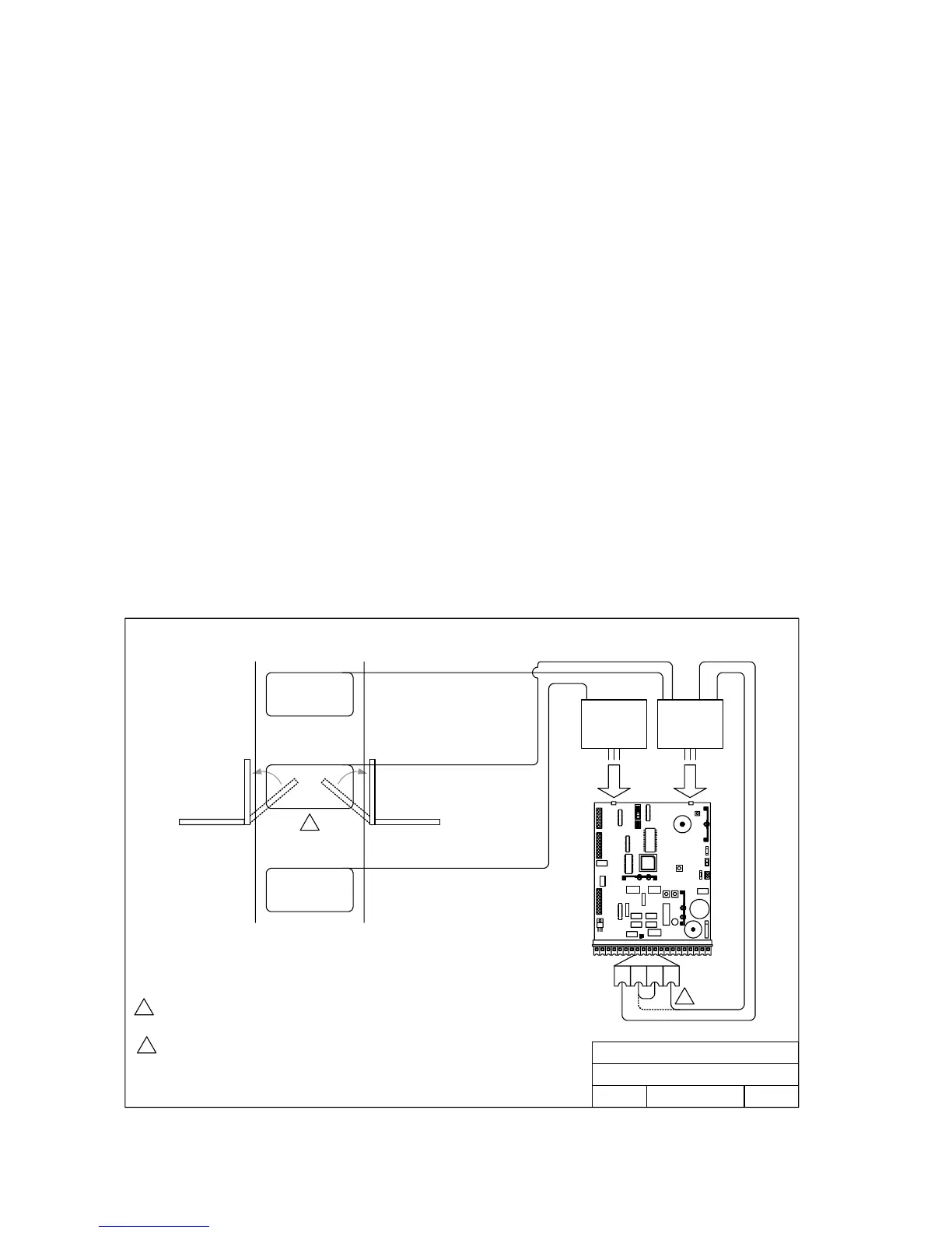
• Loop detector wiring is shown for DoorKing model 9405 and 9406 Plug-In loop detectors
only. If other loop detectors are used, refer to the installation instructions supplied with those
detectors for wiring requirements.
• If other loop detectors are used, all inputs to the terminal strip are NORMALLY OPEN. Use a
separate power supply to power external detectors. Be sure that power is turned off prior to
making any connections to the terminal strip.
• Loop layout shown is for a typical swing gate application with two-way traffic or one-way exit
only traffic. For one-way entry only traffic, the open loop is replaced with a second reverse
loop wired in series with the first reverse loop. The 9506 detector is not needed in this
application.
• Refer to the separate Loop Information Manual (available from DoorKing) for instructions on
installing loops or preformed loops.
• For correct SHADOW LOOP operation, jumper wire must be placed from terminal 9 to
terminal 10. SW1 switch 5 must be OFF, SW2 switch 1 must be ON and SW2 switch 2 must
be OFF.
• NOTE: Output of Shadow Loop Detector may be connected directly to terminals 8 and 9
(dotted line - no jumper required between 9 and 10) if SW 1, switch 5 is ON. However, with
this switch ON, terminal 8 becomes a shadow input (active only when the gate is FULL
OPEN) and all reversing devices connected to terminal 8 will operate as shadow
devices. If this is not desirable, wire the shadow loop detector as instructed in the above.
DOORKING, INC., INGLEWOOD, CA 90301
Title:
Date: Rev.Dwg. No.
Loop and Loop Detector Wiring
A
7/03 M6001-065-6
1
2
Shadow loop will only hold the gate in the open position when a vehicle is present. Shadow
loop WILL NOT reverse the gate during the close cycle.
1
Solid line shows connection with terminal 8 setup as a standard reverse input (SW1, Sw 5 OFF). If
terminal 8 is setup as a shadow reverse input (SW1, Sw 5 ON), output of loop detector can be
connected directly to terminals 8, 9 and no jumper between 9, 10.
2
TB 1
TB 2
C
NC
NO
Loop Detector
P/N 9405-010
TB 1
Loop Detector
P/N 9406-010
Exit
Reverse
REVERSE LOOP
SHADOW LOOP
EXIT LOOP
10 118 9
Figure 17
Page 24