30 734 Installation and Programming Guide | Digital Monitoring Products, Inc.
• DMP recommends using 18or 22‑gauge unshielded wire for all keypad
and AX‑Bus/LX‑Bus circuits. Do not use twisted pair or shielded wire for
AX‑Bus/LX‑Bus and Keypad Bus data circuits. All 22‑gauge wire must be
connected to a power‑limited circuit and jacket wrapped.
• On Keypad Bus circuits, to maintain auxiliary power integrity when using
22‑gauge wire do not exceed 500ft. When using 18‑gauge wire do not exceed
1,000ft. To increase the wire length or to add devices, install an additional power
supply that is listed for Fire Protective Signaling, power limited, and regulated
(12/24VDC nominal) with battery backup.
Note: Each panel allows a specific number of supervised keypads. Add
additional keypads in the unsupervised mode.
• Maximum distance for any one bus circuit (length of wire) is 2,500ft regardless
of the wire gauge. This distance can be in the form of one long wire run or
multiple branches with all wiring totaling no more than 2,500ft. As wire distance
from the panel increases, DC voltage on the wire decreases. Maximum number of
AX‑Bus/LX‑Bus devices per 2,500ft circuit is 40.
• Maximum voltage drop between the panel (or auxiliary power supply) and any
device is 2VDC. If the voltage at any device is less than the required level, add
an auxiliary power supply at the end of the circuit. When voltage is too low, the
devices cannot operate properly.
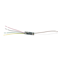
For additional information refer to the panel’s Installation Guide or the 710 Installation
Sheet (LT‑0310).
KEYPAD BUS WIRING SPECIFICATIONS