14 734 Installation and Programming Guide | Digital Monitoring Products, Inc.
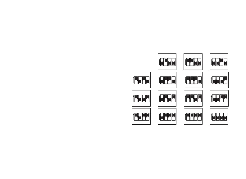
Set the 734 Address
To set the 734 address, move the DIP switches on the PCB to the appropriate
positions. See the following sections, Figures 10 and 11, and Table2 to determine
how to set keypad bus or AX‑Bus addresses.
7
Keypad Bus Addresses Explained
Each keypad bus address can
accommodate one door output and
four expansion zones.
A 734 with an address of 2 on the
keypad bus would represent door2
and zones21‑24. A 734 with a keypad
address of 14 would represent door14
and zones141‑144.
ON
1 2 3 4
ON
1 2 3 4
ON
1 2 3 4
ON
1 2 3 4
ON
1 2 3 4
ON
1 2 3 4
ON
1 2 3 4
ON
1 2 3 4
ON
1 2 3 4
ON
1 2 3 4
ON
1 2 3 4
ON
1 2 3 4
ON
1 2 3 4
ON
1 2 3 4
ON
1 2 3 4
2 3 4
5 6 7 8
9 10 11 12
13 14 15 16
Figure10: Keypad Bus Addresses