Digital Monitoring Products, Inc. | 734 Installation and Programming Guide 5
Wire the Magnetic Lock
The 734 provides a Form C (SPDT) relay for controlling locks and other
electronically‑controlled barriers. The three relay terminals marked NO C NC allow
you to connect the device wiring to the relay for module control.
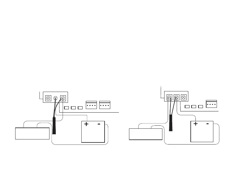
Use an additional power supply to power magnetic locks and door strikes. See
Figures 3 and 4 for typical magnetic lock and door strike wiring.
The Form C relay draws up to 35mA of current and contacts are rated for 10Amps
(resistive) at 12/24VDC. When connecting multiple locks to the Form C relay, the
total current for all locks cannot exceed 10Amps. If the total current for all locks
exceeds 10Amps, problems may arise and an isolation relay may be needed. See the
Isolation Relay section for information.
2
PROG
J2
RED RED
KYPD IN
J4
J1
DATA
XMT LED
WIEGAND
READ LED
RELAY
ON
NCCNO
GRNYELRED
Model 333
Suppressor
Normally Closed
–
+
Magnetic Door Lock
12/24 VDC
Power Supply
PROG
J2
RED
J1
DATA
XMT LED
WIEGAND
READ LED
RELAY
ON
NCCNO
GRNYELRED
Model 333
Suppressor
Normally Open
–+
DC Door Strike
12/24 VDC
Power Supply
Figure4: Typical Door Strike WiringFigure3: Typical Magnetic Lock Wiring