Digital Monitoring Products, Inc. | 734 Installation and Programming Guide 11
Connect a Card Reader (optional)
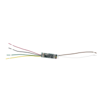
The 734 provides direct 12/24VDC, 200mA output to the reader on the Red
terminal connection. Figure9 shows a reader with wire colors RED, WHT, GRN, and
BLK connecting to terminals 1, 2, 3, and 4.
The green wire carries Data Zero (D0), and the white wire carries Data One (D1).
The red wire connects 12/24VDC, 200mA maximum power and the black wire is
ground.
The wire colors may be dierent depending on the reader being installed. Refer to
the literature provided with the reader for wire coding, wire distance, cable type
(such as shielded), and other specifications.
Card Reader LED Operation
To provide visual indication of a valid card read, the card reader can be wired to
illuminate the green LED for the duration of the door strike.
Connect the orange or brown wire to LC terminal5 to have the green LED stay on
for the duration of the relay activation.
Card Reader Annunciation
Connect the yellow wire to RA terminal6 to have the remote annunciator turn on
anytime the panel instructs the 734 onboard piezo to turn on.
6