XR200/XR2400F Programming Guide Digital Monitoring Products
39
17.1 Diagnostics function
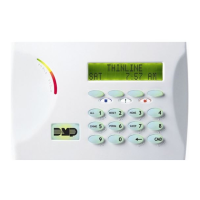
The panel contains a Diagnostics function that allows test the communication integrity of the LX-Bus™, identify
individual zones, and also display the present electrical state of any zone. To use Diagnostics, reset the panel, enter
the Diagnostics code 2313 (DIAG), and press COMMAND.
Test LX-Bus
The first Diagnostic function you will see displayed is TEST LX-BUS. This function allows you to test the ability of
the 462N, 462P, 472, and 481 Interface Cards to communicate with zone and output expander modules connected to
their LX-Bus™ circuits.
To continue, press any top row Select key. The keypad displays LX-BUS 1 2. Press the Select key under 1 to test
LX-Bus™ circuit number 1. Press the Select key under 2 to test LX-Bus circuit number 2. The keypad now displays
ADDRESS: - . Enter a 2-digit LX-Bus address to which you have assigned a device and press COMMAND.
Important Note: A device address is not the same as a zone number. If you are testing 714 or 715 Zone Expander
Modules, which each contain four zones, the device address is the first zone number. When the panel polls a 714 or
715 on the LX-Bus™, it recognizes them as four zone devices and skips polling the remaining three zones (these are
polled internally by the module, which then transmits any status changes to the panel). This polling of addresses
greatly reduces the amount of time it takes the panel to poll all devices on the LX-Bus™.
When testing LX-Bus™ devices, enter only the addresses to which the modules have been set.
The keypad next displays TESTING . . . STOP during the testing of the device. At any time, you can press the
Select key under STOP to end the polling. The panel now records the number of no responses from the device. If all
polls are received back by the panel correctly, the keypad displays 00000/65535 FAIL. The 0 (zero) represents the
number of failed polling responses.
If one or more polling attempts fail, the keypad displays * * * * */65535 FAIL. (The * * * * * represents the number of
polling attempts that failed.) A display of 65535/65535 FAIL indicates a problem with the interface card or its LX-
Bus™ wiring such as a bad or broken wire, harness not properly connected, or excessive noise or distance. It can also
mean that a zone number was entered that did not match a device address. Press the Back Arrow key to enter a new
device address or press COMMAND to exit the TEST LX-BUS option.
Zone Finder
The second Diagnostic function is the Zone Finder. Press the COMMAND to display ZONE FINDER. This function
allows you to identify individual zones on devices connected to the LX-Bus™ of an interface card, the panel, or any
zones on the keypad data bus. To use ZONE FINDER, press any top row Select key. The display changes to FAULT
ZONE. The next zone on the system that changes from a normal to an open or shorted state is displayed as ZONE
NO: * * *. To continue, press the Back Arrow key.
Zone State
Press the COMMAND to display the third Diagnostic function: ZONE STATE. This function allows you to enter any zone
number and check its current electrical state (Normal, Open, or Shorted). Press any Select key. The display changes
to ZONE NUMBER: _ . Enter in the number of the zone you want to check and press COMMAND. The panel then
displays the current state of the zone as either NRML (normal), OPEN, or SHORT.
17 - APPENDIX
 Loading...

