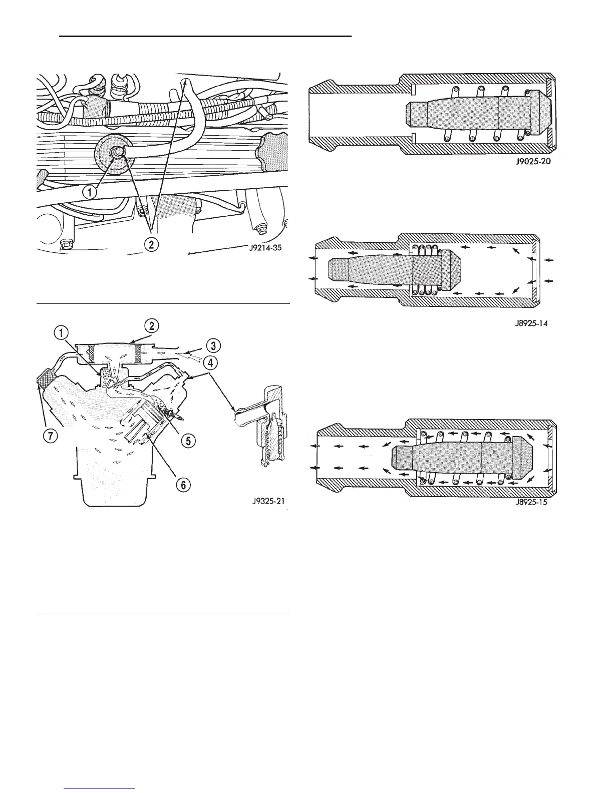
routed into the combustion chamber based on intake
manifold vacuum.
When the engine is not operating or during an
engine pop-back, the spring forces the plunger back
against the seat. This will prevent vapors from flow-
ing through the valve.
During periods of high manifold vacuum, such as
idle or cruising speeds, vacuum is sufficient to com-
pletely compress spring. It will then pull the plunger
to the top of the valve (Fig. 7). In this position there
is minimal vapor flow through the valve.
During periods of moderate manifold vacuum, the
plunger is only pulled part way back from inlet. This
results in maximum vapor flow through the valve
(Fig. 8).
POSITIVE CRANKCASE VENTILATION (PCV)
SYSTEM—4.7L ENGINE
DESCRIPTION
The 4.7L V-8 engine is equipped with a closed
crankcase ventilation system and a Positive Crank-
case Ventilation (PCV) valve.
This system consists of:
• a PCV valve mounted to the oil filler housing
(Fig. 9). The PCV valve is sealed to the oil filler
housing with an o-ring.
• the air cleaner housing
• two interconnected breathers threaded into the
rear of each cylinder head (Fig. 10).
• tubes and hose to connect the system compo-
nents.
Fig. 4 PCV Valve/Hose—Typical
1 – PCV VALVE
2 – PCV VALVE HOSE CONNECTIONS
Fig. 5 Typical Closed Crankcase Ventilation System
1 – THROTTLE BODY
2 – AIR CLEANER
3 – AIR INTAKE
4 – PCV VALVE
5 – COMBUSTION CHAMBER
6 – BLOW-BY GASES
7 – CRANKCASE BREATHER/FILTER
Fig. 6 Engine Off or Engine Pop-Back—No Vapor
Flow
Fig. 7 High Intake Manifold Vacuum—Minimal Vapor
Flow
Fig. 8 Moderate Intake Manifold Vacuum—Maximum
Vapor Flow
DN EMISSION CONTROL SYSTEMS 25 - 27
DESCRIPTION AND OPERATION (Continued)